2. Code the jump table with jump instructions to each individual USB interrupt ser-
vice routine. This table has two important requirements, arising from the format of
the AVEC byte (zero-based, with 2 LSBs set to 0):
•
•
•
•
It must begin on a page boundary (address 0xNN00).
The jump instructions must be four bytes apart.
The interrupt service routines can be placed anywhere in memory.
Write initialization code to enable the USB interrupt (INT2), and Autovector-
ing.
8051 USB
Interrupt
Vector
USB_Jmp_Table:
LJMP
0043
0400
04
0044
0045
(00)2C
USB core
2C
LJMP EP2OUT_ISR
042C
042D
042E
01
19
AVEC
EP2OUT_ISR:
0119
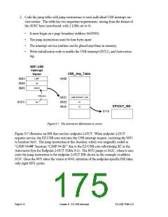
Figure 9-7. The Autovector Mechanism in Action
Figure 9-7 illustrates an ISR that services endpoint 2-OUT. When endpoint 2-OUT
requires service, the EZ-USB core activates the USB interrupt request, vectoring the 8051
to location 0x43. The jump instruction at this location, which was originally coded as
“LJMP 04-00” becomes “LJMP 04-2C” due to the EZ-USB core substituting 2C as the
Autovector byte for Endpoint 2-OUT (Table 9-3). The 8051 jumps to 042C, where it exe-
cutes the jump instruction to the endpoint 2-OUT ISR shown in this example at address
0119. Once the 8051 takes the vector at 0043, initiation of the endpoint-specific ISR takes
only eight 8051 cycles.
Page 9-12
Chapter 9. EZ-USB Interrupts
EZ-USB TRM v1.9

 CYPRESS [ CYPRESS ]