CBC915 EnerChip Energy Processor
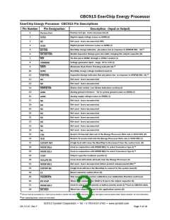
EnerChip Energy Processor CBC915 Pin Descriptions
Pin Number
Pin Designation
Description - (Input or Output)
1
Factory test pin - leave unconnected (I)
Factory Test
2
Digital supply voltage (same as AVDD) (I)
DVDD
3
Not used - leave unconnected (NC)
NC
4
Digital ground reference (same as AVSS) (I)
DVSS
5
EnerChip charge indicator, pin pulses low in response to STATUS SW/ (O) (1)
Enable Capacitor Charge goes low while charging the output capacitor (O)
Tie this pin to DVDD through a 100kΩ resistor (I)
Voltage generator input - range 0V to 2.5V (I)
EC CHG
EN CAP CHG
RST
6
7
8
VGSENSE
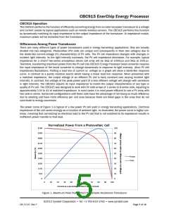
MPPT
9
Maximum Peak Power Tracking indicator (O) (1)
EnerChip charge voltage feedback input (I)
10
11
12
13
14
15
16
17
18
19
20
21
22
23
24
25
26
27
28
29
30
31
32
33
34
35
36
37
38
ECFB
Capacitor Charge indicator; this pin pulses low in response to STATUS SW/ (O) (1)
Not used - leave unconnected
CAP CHG
NC
Not used - leave unconnected
NC
Status state switch (see Status Indicators section) (I)
Analog ground reference - tie to system ground (same as DVSS) (I)
Analog supply voltage (same as DVDD) (I)
STATUS SW
AVSS
AVDD
Not used - leave unconnected
NC
Not used - leave unconnected
NC
Not used - leave unconnected
NC
Not used - leave unconnected
NC
Not used - leave unconnected
NC
Not used - leave unconnected
NC
Not used - leave unconnected
NC
Not used - leave unconnected
NC
Serial I/O transmit data out of the Energy Processer Data rate is 9600 8N1 (O)
Serial I/O receive data into the Energy Processer Data rate is 9600 8N1 (I)
A high level will cause the EnerChip to disconnect from the system load (O)
Used in conjunction with MODE SEL1 to select transducer type (I) (2)
Used in conjunction with MODE SEL0 to select transducer type (I) (2)
Output capacitor feedback monitor (I)
TXD
RXD
CUTOFF RST
MODE SEL0
MODE SEL1
VCAP
A low level will isolate all loads from the Energy Processer (0)
Not used - leave unconnected (future product enhancement) (NC) (2)
A high level will force the EnerChip to connect to the system load (O)
Boost converter switch driver (O)
ISOLATE EN
MODE SEL2
CUTOFF EN
LX
Only used in target system calibration (see Calibration Function section) (I)
When high connects the VCAP A/D pin to the output capacitor (O)
Used to select output priority or battery priority mode (I) (2) (not on CBC915-ACA)
When low connects power to the application system (O)
CALIBRATE
EN VCAP
MODE SEL3
EN VOUT
(1) This pin must be connected to a 1 kohm pull-up resistor or resistor with series LED to the positive supply. See Figure 3 and the section titled “Status Indicators” for more information.
(2) See “Operating Modes” section for more detail.
©2012 Cymbet Corporation • Tel: +1-763-633-1780 • www.cymbet.com
DS-72-15 Rev F
Page 3 of 16

 CYMBET [ CYMBET CORPORATION ]