EnerChip Solar Energy Harvesting Demo Kit
Guidelines for Attaching Other Energy Harvesting Transducers
Other energy harvesting transducers (e.g., inductive, piezoelectric, thermoelectric) may be attached to the CBC-
EVAL-08. As configured, the CBC-EVAL-08 will operate with many other transducer types. However, performance
specifications of these other transducers - namely output impedance - will affect the power conversion
efficiency of the CBC-EVAL-08 kit as designed. Please contact Cymbet Applications Engineering at the phone
number shown below to discuss your specific application and desired alternate transducer(s).
The CBC5300 module is designed to work with transducers having an output impedance over the range of 50Ω
to 4kΩ and an input voltage range of 270mV to 1.5V The minimum open circuit voltage to start operation is
700mV. The nominal voltage and impedance is 800mV at 1kΩ. Operating characteristics for most transducer
types are typically available from the manufacturer’s data sheet. Output impedance, operating voltage, and
peak power point can also be verified by empirical measurements. To do this, measure the load voltage and
current as a variable load impedance across the transducer is swept over a broad enough range where the
peak power point can be found by finding the maximum product of the measured load voltage and current.
To configure the CBC5300 to work with a given transducer, the optimal transducer operating voltage point must
first be obtained though the manufacturer’s data sheet or from empirical measurements. Next calculate the
values needed for a voltage divider to set the operating voltage point on the VOPER pin (pin 10 of J6). The top of
the voltage divider uses VREG (pin 11 of J6) as its voltage source; the bottom of the voltage divider is connected
to ground. VOPER is equal to VREG * (R2 / (R1 + R2)), where VREG is nominally 4.06V and R2 (bottom resistor)
is in the range of 500kΩ to 1MΩ with the optimal value around 750kΩ. Note: Better circuit performance (i.e.,
less input ripple voltage) will be obtained if R2 is made smaller than 750kΩ. A more useful formula is: R1 =
R2 * ((VREG / VOPER) - 1). Example: For a 1kΩ photovoltaic cell with operating voltage of 800mV, R1 can be
determined as R1 = 732kΩ * ((4.06V / 800mV) - 1) = 2.98MΩ. A 3.01MΩ resistor is the nearest standard
value. R2 was chosen as a standard resistor value. 750kΩ for R2 is also a standard resistor value but the
VOPER voltage will be further away from nominal due to the standard resistor values available for R1.
Capacitor C1 (22µF) is used to set the bandwidth of the boost converter control loop. If a low impedance
transducer is used the value of C1 might have to be reduced in value. This can be verified using an oscilloscope
to check the waveform on GATE (pin 3 of J6). The waveform should be three pulses followed by a longer
interval, followed again by three pulses. The three pulses will have approximately 16.7µs of high duration
followed by 16.7µs of low duration. If more than three pulses are in the waveform then the value of C1 should
be reduced to obtain the nominal waveform.
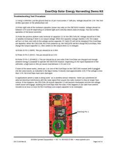
When using a power transducer other than the solar cell supplied with the CBC-EVAL-08, it is recommended
that the solar cell be isolated from the input stage prior to connecting the other transducer. This is easily
done by cutting trace connector J7. The alternate transducer can then be used as the input power transducer
by connecting it across connector PT1 if using an AC transducer such as a piezoelectric element, or, across
connector J8 if using a DC transducer - for example, a different solar cell. For more efficient performance, follow
the recommendations given earlier in this section. If multiple transducer types are to be used - for example,
a solar cell and a piezoelectric transducer, or a solar cell and a thermoelectric generator - contact Cymbet
Applications Engineering for design support.
System Level Considerations when Using a Low Power Energy Harvester
The CBC5300 is capable of supplying 10s to 100s of µW of continuous power to the load. Most applications
operating with radios and microcontrollers typically need 10s to 100s of mW of power under peak load
conditions. The disparity between what is available and what is needed can be made up by limiting the
amount of time the load is powered and waiting sufficient time for the energy harvester to replenish the energy
storage device before the subsequent operation commences. In typical remote RF sensor applications, the
‘on’ time will be on the order of 5-20ms, with an ‘off’ time of several seconds to several hours depending on
the application and available energy source. The duty cycle is an important consideration when designing a
wireless system.
©2009 Cymbet Corporation • Tel: +1-763-633-1780 • www.cymbet.com
DS-72-08 Rev18
Page 7 of 11

 CYMBET [ CYMBET CORPORATION ]