AN-1043: EnerChip™ CC as Backup Power for a DS1390 RTC
Circuit Description and Operation
Under normal operation, the RTC derives its power from the main system supply, which might be a large coin
cell, prismatic cell, cylindrical batteries, or indirectly from wall power through a voltage regulator. Because the
EnerChip has very low self-discharge, it needs to be charged only after it has been used in the performance
of its duty as a backup power source or on a very infrequent basis to keep it fully charged when not being
used. To maintain a charge of 90% or greater on the EnerChip when it has not been used as a backup power
source for prolonged periods, the EnerChip needs no more than one hour of charging time per month. Such
a low charging duty cycle would present a negligible parasitic load to the main power source, as the EnerChip
charges quickly and its charging current decays to just a few nanoamperes when fully charged. It is important
that the DS1390 registers assigned to the trickle charge function for the backup power source not be enabled.
The EnerChip CC controls the EnerChip charging function internally.
When main power is interrupted - as during line power outages or when the main battery is removed for
recharging or replacement, the backup power source provides enough energy to maintain operation of the real-
time clock.
The EnerChip CC is a surface mount device that contains a rechargeable battery with integrated battery
management that performs the charge control, discharge control, threshold voltage detection, and supply
supervisory functions all in one low profile package. It operates over the range of 2.5V to 5.5V and the
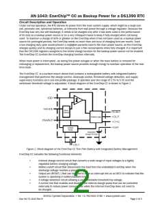
switchover threshold voltage is adjustable. A block diagram of the EnerChip CC is shown in Figure 2.
Figure 2. Block diagram of the EnerChip CC Thin Film Battery with Integrated Battery Management
EnerChip CC includes the following functional elements:
•
•
•
Internal charge control circuit that converts a wide range of input voltages to a tightly
regulated battery charging voltage;
Battery cutoff circuit that disconnects the load from the embedded EnerChip when the
discharge voltage reaches a preset limit;
Output pin (RESET/) that can be used to drive an interrupt line on an MCU to indicate that the
system is operating in battery-backed mode;
•
•
A voltage detection circuit allowing a user-selectable threshold trip voltage;
A control line that enables and disables the internal charge pump that can be controlled
externally to reduce power consumption when the internal EnerChip does not need to
be charged.
©2011 Cymbet Corporation • Tel: +1-763-633-1780 • www.cymbet.com
Doc AN-72-1043 Rev B
Page 2 of 3

 CYMBET [ CYMBET CORPORATION ]