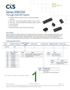
Series 209/210
Through-Hole DIP Switch
Electrical Specifications
Parameter
Conditions & Remarks
Min
Max
Unit
Operating Temperature
Range
-40
+85
°C
Switch Function
Circuit
SPST
2
12
positions
milliohms
Initial
At end of life
Initial
At end of life
25
50
100
500
Contact Resistance (209)
Contact Resistance (210)
Insulation Resistance
Dielectric Strength
milliohms
megohms
minute
Between insulated terminals
500 VAC between adjacent
switches
1000
1
100mA @ 20 VDC or
.1mA @ 5 VDC(dry circuit)
100mA @ 20 VDC or
.1mA@5 VDC(dry circuit)
Between adjacent closed
switches
Actuation Life (209)
Actuation Life (210B)
Switch Capacitance
2,000
1,000
5.0
cycles
cycles
pF
100
or
50
mA
or
VDC
Non-switching Rating
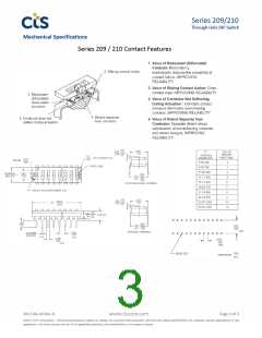
Mechanical and Environmental
Soldering
MSL
Maximum wave temperature, 260°C for 5 seconds
Level 1
Lead-Free. Fully compliant to RoHS Directive 2011/65/EU
Per MIL-STD-202F, method 213B, condition A (50G’s)
with no contact inconsistencies greater than 1 microsecond
RoHS
Shock
Per MIL-STD-202F, method 204D, condition B (.06” or 15G’s between 10 HZ to 2K HZ) with
no contact inconsistencies greater than 1 microsecond
Bottom seal standard, optional top tape seal for board spray washing
Special top marking available-consult CTS
Vibration
Seal
Marking
Packaging:
Storage Temperature
Range
Standard anti-static tube packaging
-40°C to +85°C
2017-06-16 Rev. B
Page 2 of 3
© 2017 CTS® Corporation. Information/product(s) subject to change. No warranty that product(s) will meet the stated specifications for customer specific applications or test
equipment. Visit www.ctscorp.com for list of applicable patent(s), more information, or to request a quote.

 CTS [ CTS ]