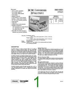
MRH SERIES
15 WATT
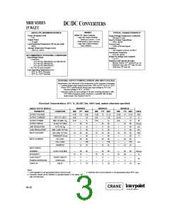
DC/DC CONVERTERS
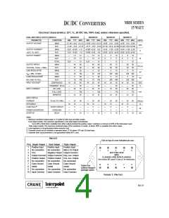
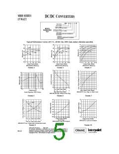
Electrical Characteristics: 25°C Tc, 28 VDC Vin, 100% load, unless otherwise specified.
DUAL AND TRIPLE OUTPUT MODELS
MRH2812D
MRH2815D
MRH2812T
MIN TYP MAX
MRH2815T
PARAMETER
CONDITION
MIN TYP MAX
MIN TYP MAX
MIN TYP MAX
UNITS
OUTPUT VOLTAGE
MAIN
AUX.
+11.88 +12.0 +12.12 +14.85 +15.0 +15.15 +4.95 +5.0 +5.05 +4.95 +5.0 +5.05
–11.82 –12.0 –12.18 –14.77 –15.0 –15.23 ±11.50 ±12.0 ±12.50 ±14.40 ±15.0 ±15.60
VDC
1
OUTPUT CURRENT
MAIN
+0.01 +0.625 +1.0
–0.01 –0.625 –1.0
+0.008 +0.50 +0.8
–0.008 –0.50 –0.8
+0.40 +1.80 +2.00 +0.40 +1.80 +2.00
±0.00 ±0.25 ±0.50 ±0.00 ±0.20 ±0.40
A
–55°C TO +85°C
AUX.
1
OUTPUT POWER
MAIN
—
—
7.5
7.5
—
40
40
5
12
12
—
—
7.5
7.5
—
40
40
5
12
12
2
0
9
3
10
6
2
0
9
3
10
6
AUX.
W
TOTAL
0.25
—
15
0.25
—
15
2
–
15
75
50
10
400
10
400
36
40
80
770
25
2
–
15
50
50
10
OUTPUT RIPPLE
MAIN
60
60
–
50
30
5
–
30
30
5
mV p-p
mV
VOLTAGE, 10 kHz - 2 MHz
LINE REGULATION
AUX.
—
60
—
60
–
–
MAIN
—
20
—
20
—
—
—
—
16
—
—
—
—
—
—
—
—
16
—
—
—
—
V
= MIN. TO MAX.
AUX.
—
20
5
100
30
—
20
5
100
30
200
5
250 500
10
250 500
IN
2
LOAD REGULATION
NO LOAD TO FULL
MAIN
—
—
5
mV
AUX.
—
10
28
—
55
—
22
100
40
—
10
28
—
55
—
22
100
40
200
28
—
70
—
23
3
INPUT VOLTAGE
CONTINUOUS
TRANSIENT 50 ms
NO LOAD
FULL LOAD
INHIBITED
16
—
19
—
28
—
85
—
23
36
40
VDC
V
50
50
INPUT CURRENT
—
70
—
70
95
—
700
25
—
700
25
778
25
mA
—
—
INPUT RIPPLE
CURRENT
10 kHz TO 2 MHz
—
76
—
—
—
25
78
5
50
—
—
—
10
—
76
—
—
—
25
78
5
50
—
—
—
10
—
70
—
—
—
25
72
5
50
—
—
—
10
—
70
—
—
—
25
72
5
50
—
—
—
10
mA p-p
%
EFFICIENCY
4
LOAD FAULT
SHORT CIRCUIT
OVERLOAD
DELAY
W
POWER DISSIPATION
START-UP
5
5
5
5
3
3
3
3
ms
Notes
1. Maximum combined output power is 15 watts for both dual and triple models.
Dual output models: The maximum specification is the total output current/power.
Up to 80% of that total is available from either output provided the positive output maintains a minimum of 20% of the total power used.
Triple output models: The maximum combined power of the auxiliaries is 6 watts, of which 100% is available from either output.
2. Load regulation is not guaranteed below minimum load.
4
3. Converter should not be inhibited or operated below 12 Vin above 10 rads (Si) total dose.
4. Indefinite short circuit protection is not guaranteed above 85°C case.
PIN OUT
Dot on top of cover indicates pin one.
Pin Single Output
Dual Output
Positive Input
No connection
Triple Output
Positive Input
Main (+5) Output
1
2
3
4
5
6
7
8
9
Positive Input
No connection
Trim
1
2
3
4
5
Negative Output Output Common
BOTTOM VIEW
MRH
FLANGED AND NON-FLANGED
Output Common Output Common Neg. Aux. Output
Positive Output Positive Output Pos. Aux. Output
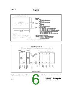
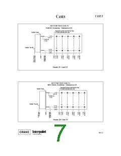
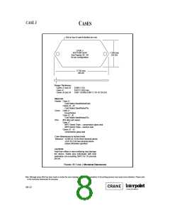
See Section B8, cases F3 and J3, for dimensions.
No connection
Case Ground
Inhibit
No connection
Case Ground
Inhibit
No connection
Case Ground
Inhibit
10
9
8
7
6
Dotted line
outlines flanged
package option.
No connection
No connection
Input Common
No connection
Input Common
10 Input Common
FIGURE 1: PIN OUT
B4-21

 CRANE [ Crane Aerospace & Electronics. ]