/RZꢃ9ROWDJHꢃ9ꢇꢈꢉꢊ.ꢀꢁIOH[ꢊ9ꢇꢄꢆꢊ9ꢇꢄꢋELVꢃ0RGHPꢃ'DWDꢃ3XPSV
53ꢀꢁ'ꢂꢃ53ꢄꢄꢁ'ꢂꢃDQGꢃ53ꢅꢆꢆ'
Automatic Mode Selection
1
When automatic mode selection (AMS) is enabled, the
MDP configures itself to the highest compatible data rate
supported by the remote modem (AUTO bit). Automode
operation is supported in V.90, K56flex, V.34, V.32 bis,
RTS-CTS Response
Constant Controlled
Turn-Off
Sequence
N/A
Configuration
Carrier
Carrier
3
V.32 V.22 bis, V.22, V.21, V.23, Bell 212A, and Bell 103
modes.
V.90, K56flex, V.34,
V.32 bis, V.32
± 2 ms
N/A
V.33/V.17 Long
V.33/V.17 Short
V.29
N/A
N/A
2
4
1393 ms
15 ms
Automatic Rate Adaption (ARA)
2
4
In V.90, K56flex, V.34, and V.32 bis modes, automatic
rate adaption (ARA) can be enabled to select the highest
data rate possible based on the measured eye quality
monitor (EQM) (EARC bit). This selection occurs during
handshake/retrain and rate renegotiation.
142 ms
253 ms
708 ms
15 ms
N/A
2
12 ms
V.27 4800 Long
V.27 4800 Short
V.27 2400 Long
V.27 2400 Short
N/A
2
4
7 ms
N/A
2
4
50 ms
7 ms
Tone Generation
N/A
2
4
943 ms
10 ms
The MDP can generate single or dual voice-band tones
from 0 Hz to 3600 Hz with a resolution of 0.15 Hz and an
accuracy of ± 0.01%. Tones over 3000 Hz are attenuated.
DTMF tone generation allows the MDP to operate as a
programmable DTMF dialer.
N/A
2
4
67 ms
10 ms
V.22 bis, V.22,
Bell 212A
± 2 ms
270 ms
N/A
V.21
500 ms
210 ms
500 ms
210 ms
N/A
N/A
V.23, Bell 103
Notes:
Data Encoding
The data encoding conforms to ITU-T recommendations
V.90, V.34, V.32 bis, V.32, V.17, V.33, V.29, V.27 ter,
V.22 bis, V.22, V.23, or V.21, and is compatible with Bell
208, 212A, or 103, depending on the model and selected
configuration.
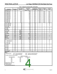
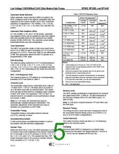
1. Times listed are CTS turn-on. The CTS OFF-to-ON
response time is host programmable in DSP RAM. (Full-
duplex modes only.)
2. Add echo protector tone duration plus 20 ms when echo
protector tone is used during turn-on.
RTS - CTS Response Time
3. Turn-off sequence consists of transmission of remaining
data and scrambled ones for controlled carrier operation.
CTS turn-off is less than 2 ms for all configurations.
The response times of CTS relative to a corresponding
transition of RTS are listed in Table 3.
4. Plus 20 ms of no transmitted energy.
5. N/A = not applicable.
Transmit Level
The transmitter output level is selectable from 0 dBm to
-15 dBm (VAA = +5V) in 1 dB steps and is accurate to
±0.5 dB when used with an external hybrid. The output
level can also be fine tuned by changing a gain constant
in MDP DSP RAM. The maximum V.34/V.32 bis/V.32
transmit level for acceptable receive performance should
not exceed -9 dBm.
Receive Level
The MDP satisfies performance requirements for received
line signal levels from –9 dBm to –43 dBm measured at
the Receiver Analog (RXA) (TIP and RING) input (-15
dBm at RIN).
Note: In V.34 mode, the transmit level may be
automatically changed during the handshake. This
automatic adjustment of the transmit level may be
disabled via a parameter in DSP RAM.
Note: A 6 dB pad is required between TIP and RING and
the RIN input.
Receiver Timing
Transmitter Timing
The timing recovery circuit can track a frequency error in
the associated transmit timing source of ±0.035% (V.22
bis) or ±0.01% (other configurations).
Transmitter timing is selectable between internal
(±0.01%), external, or slave.
Carrier Recovery
Scrambler/Descrambler
The carrier recovery circuit can track a ±7 Hz frequency
offset in the received carrier.
A self-synchronizing scrambler/descrambler is used in
accordance with the selected configuration.
Clamping
Answer Tone
Received Data (RXD) is clamped to a constant mark
whenever the Received Line Signal Detector (~RLSD) is
off. ~RLSD can be clamped off (RLSDE bit).
When the NV25 bit is a zero, the MDP generates a 2100
Hz answer tone at the beginning of the answer handshake
for 5.0 seconds (V.8) or 3.6 seconds (V.32 bis, V.32, V.22
bis, V.22, V.23, and V.21). The answer tone has 180°
phase reversals every 0.45 second to disable network
echo cancellers (V.8, V.32 bis, V.32).

 CONEXANT [ CONEXANT SYSTEMS, INC ]