Document 528-2
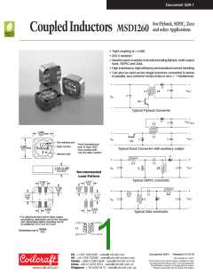
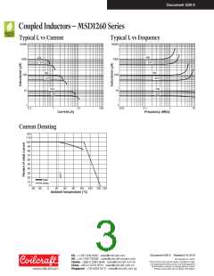
Coupled Inductors – MSD1260 Series
Irms(A)
Coupling
Leakage
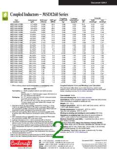
Part
Inductance2
(µH)
DCRmax3
(Ohms)
SRFtyp4
(MHz)
coefficient Inductance5
Isat6
(A)
both
one
number1
typ
typ(µH)
windings7 winding8
MSD1260-472ML_
MSD1260-562ML_
MSD1260-682ML_
MSD1260-822ML_
MSD1260-103ML_
4.7 20ꢀ
5.6 20ꢀ
6.8 20ꢀ
8.2 20ꢀ
10 20ꢀ
0.036
0.040
0.048
0.052
0.060
32.0
31.0
28.0
25.0
22.0
0.98
0.98
0.98
0.98
0.99
0.20
0.20
0.24
0.25
0.26
10.3
9.66
9.21
8.55
7.40
3.16
3.00
2.75
2.63
2.45
4.47
4.24
3.88
3.72
3.46
MSD1260-123ML_
MSD1260-153ML_
MSD1260-183ML_
MSD1260-223ML_
MSD1260-273ML_
12 20ꢀ
15 20ꢀ
18 20ꢀ
22 20ꢀ
27 20ꢀ
0.074
0.085
0.097
0.116
0.124
21.0
17.6
17.0
15.0
13.6
0.99
0.99
0.99
0.98
0.99
0.28
0.32
0.40
0.68
0.50
6.86
6.09
5.30
5.01
4.66
2.21
2.06
1.93
1.76
1.70
3.12
2.92
2.73
2.49
2.41
MSD1260-333ML_
MSD1260-393ML_
MSD1260-473ML_
MSD1260-563ML_
MSD1260-683ML_
33 20ꢀ
39 20ꢀ
47 20ꢀ
56 20ꢀ
68 20ꢀ
0.134
0.142
0.174
0.198
0.216
12.7
11.7
8.7
7.6
6.1
0.99
0.99
0.99
0.99
>0.99
0.65
1.09
0.80
0.75
0.57
4.22
3.80
3.25
3.07
2.83
1.64
1.59
1.44
1.35
1.29
2.32
2.25
2.03
1.91
1.83
MSD1260-823ML_
MSD1260-104ML_
MSD1260-124KL_
MSD1260-154KL_
MSD1260-184KL_
82 20ꢀ
100 20ꢀ
120 10ꢀ
150 10ꢀ
180 10ꢀ
0.274
0.322
0.418
0.476
0.536
5.3
5.0
4.4
4.0
3.6
0.99
0.99
0.99
0.99
0.99
1.52
1.41
1.34
1.52
1.80
2.55
2.20
2.05
1.82
1.60
1.15
1.06
0.93
0.87
0.82
1.62
1.50
1.31
1.23
1.16
MSD1260-224KL_
MSD1260-274KL_
MSD1260-334KL_
MSD1260-394KL_
MSD1260-474KL_
220 10ꢀ
270 10ꢀ
330 10ꢀ
390 10ꢀ
470 10ꢀ
0.691
0.806
1.09
1.20
1.59
3.2
2.8
2.5
2.3
2.1
>0.99
>0.99
>0.99
>0.99
>0.99
1.60
2.23
2.39
3.72
2.89
1.51
1.41
1.28
1.16
1.00
0.72
0.67
0.57
0.55
0.48
1.02
0.95
0.81
0.77
0.67
MSD1260-564KL_
MSD1260-684KL_
MSD1260-824KL_
MSD1260-105KL_
560 10ꢀ
680 10ꢀ
820 10ꢀ
1000 10ꢀ
1.81
2.06
2.65
3.06
2.0
1.8
1.5
1.2
>0.99
>0.99
>0.99
>0.99
2.55
5.76
2.86
4.32
0.95
0.88
0.79
0.69
0.45
0.42
0.37
0.34
0.63
0.59
0.52
0.49
Coupled Inductor Core and Winding Loss Calculator
1. When ordering, please specify termination and packaging codes:
MSD1260-105KLD
Termination: L = RoHS compliant matte tin over nickel over phos
bronze.
This web-based utility allows you to enter frequency, peak-to-peak
(ripple) current, and Irms current to predict temperature rise and overall
losses, including core loss. Go to online calculator.
Special order: T = RoHS tin-silver-copper (95.5/4/0.5) or
S = non-RoHS tin-lead (63/37).
Core material Ferrite
Packaging: D = 13″ machine-ready reel. EIA-481 embossed plastic
tape (500 parts per full reel).
Core and winding loss Go to online calculator
Terminations RoHS compliant matte tin over nickel over phos bronze.
Other terminations available at additional cost.
B = Less than full reel. In tape, but not machine ready.
To have a leader and trailer added ($25 charge), use
code letter D instead.
Weight: 2.8 – 3.2 g
2. Inductance shown for each winding, measured at 100 kHz, 0.1 Vrms,
0 Adc on an Agilent/HP 4284A LCR meter or equivalent.When leads
are connected in parallel, inductance is the same value.When leads are
connected in series, inductance is four times the value.
3. DCR is for each winding.When leads are connected in parallel, DCR
is half the value.When leads are connected in series, DCR is twice the
value.
Ambient temperature –40°C to +85°C with Irms current, +85°C to
+125°C with derated current
Storage temperature Component: –40°C to +125°C.
Tape and reel ackaging: –40°C to +80°C
Winding-to-winding and winding-to-core isolation 500 Vrms
Resistance to soldering heat Max three 40 second reflows at
+260°C, parts cooled to room temperature between cycles
Moisture Sensitivity Level (MSL) 1 (unlimited floor life at <30°C /
85ꢀ relative humidity)
Failures in Time (FIT) / Mean Time Between Failures (MTBF)
38 per billion hours / 26,315,789 hours, calculated per Telcordia SR-332
Packaging 500/13″ reel; Plastic tape: 24 mm wide, 0.35 mm thick,
16 mm pocket spacing, 6.6 mm pocket depth
PCB washing Tested with pure water or alcohol only. For other
solvents, see Doc787_PCB_Washing.pdf.
4. SRF measured using an Agilent/HP 4191A or equivalent.When leads
are connected in parallel, SRF is the same value.
5. Leakage Inductance is for L1 and is measured with L2 shorted.
6. DC current, at which the inductance drops 30ꢀ (typ) from its value
without current. It is the sum of the current flowing in both windings.
7. Equal current when applied to each winding simultaneously that causes
a 40°C temperature rise from 25°C ambient. See temperature rise calcu-
lation.
8. Maximum current when applied to one winding that causes a 40°C
temperature rise from 25°C ambient. See temperature rise calculation.
9. Electrical specifications at 25°C.
Refer to Doc 639 “Selecting Coupled Inductors for SEPIC Applications.”
Refer to Doc 362 “Soldering Surface Mount Components” before soldering.
Document 528-2 Revised 01/13/12
US +1-847-639-6400 sales@coilcraft.com
UK +44-1236-730595 sales@coilcraft-europe.com
Taiwan +886-2-2264 3646 sales@coilcraft.com.tw
China +86-21-6218 8074 sales@coilcraft.com.cn
Singapore + 65-6484 8412 sales@coilcraft.com.sg
© Coilcraft Inc. 2013
This product may not be used in medical or high
risk applications without prior Coilcraft approval.
Specification subject to change without notice.
Please check web site for latest information.

 COILCRAFT [ Coilcraft lnc. ]