CM119B
USB Audio Single Chip
H: With Mixer (With Default Mute) USB Descriptors are to be
change accordingly
39
40
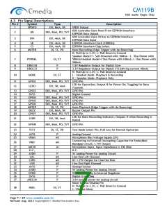
VOLUP
PDSW
DI, ST, PU
Volume Up (Edge Trigger with de-Bouncing)
Power Down Switch Control (for PMOS Polarity)
0: Normal Mode, 1: Power Down Mode
USB Data D+
DO, 4mA , OD
41
42
43
44
USBDP
USBDM
GPIO1
SCLK
AIO
AIO
USB Data D-
DIO, 8mA, PD, 5VT GPIO Pin
DIO, 8mA, PD, 5VT External MCU Serial Bus Clock Pin
External MCU Interrupt Pin
45
MINT
DO, 4mA, SR
When Register Address 4 ~ 7 has new data, MINT is set Low; after
MCU read, MINT is reset to H
DIO, 8mA, PD, 5VT External MCU Serial Bus Data Pin
46
47
48
SDAT
MCLK
External MCU Clock Pin, Clock Frequency is programmable
Default is 1.5 MHz (Options Include 6MHz, 3MHz, and 1.5MHz)
Volume Down (Edge Trigger with de-Bouncing)
DO, 4mA, SR
DI, ST, PU
VOLDN
Note: DI / DO / DIO – Digital Input / Output / Bi-Directional Pin, AI / AO / AIO – Analog Input / Output / Bi-Directional
Pin, SR – Slew Rate Control, ST – Schmitt Trigger, PD / PU – Pull Down / Pull Up, 5VT – 5 Volt Tolerant (3.3V Pin), OD –
Open Drain, P – Power Supply Pin
Page 8 / 29 www.cmedia.com.tw
Revised: Aug. 2013 Copyright© C-Media Electronics Inc.

 CMEDIA [ C-MEDIA ELECTRONICS ]