CS8900A
Crystal LAN™ Ethernet Controller
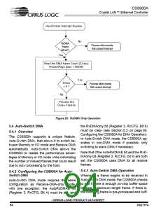
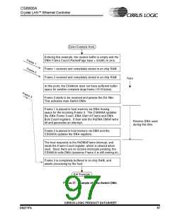
be completely received. Usually, the DMA re-
DMA Frame Count, CDMA, commits the mem-
ceive frame interrupt (RxDMAiE, bit 7, Regis- ory covered by the CDMA count, and the DMA
ter B, BufCFG) is set so that the CS8900A cannot overwrite this committed space until
generates an interrupt when a frame is trans-
the space is freed. The driver then processes
ferred by DMA. Figure 25 shows how a DMA the frames described by the CDMA count and
Receive Frame interrupt is processed.
makes a second read of the DMA frame count.
This second read frees the buffer memory
space described by the CDMA counter.
In the interrupt service routine, the BufEvent
register (register C), bit RxDMA Frame (bit 7)
indicates that one or more receive frames
During the frame processing, the software
were transferred using DMA. The software should advance the PDMA_START pointer. At
driver should maintain a pointer (e.g.
PDMA_START) that will point to the beginning
of a new frame. After the CS8900A is initial-
ized and before any frame is received, pointer
PDMA_START points to the beginning of the
DMA buffer memory area. The first read of the
the end of processing a frame, pointer
PDMA_START should be made to align with a
double-word boundary. The software remains
in the loop until the DMA frame count read is
zero.
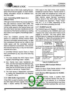
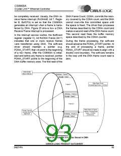
DMA Buffer
Base Address
RxStatus - Fram e 1
RxLength - Frame 1
DM A Byte Count
(PacketPage base + 012Ah)
Fram e 1
RxStatus - Fram e 2
RxLength - Frame 2
Frame 2
DMA Start of Fram e
"Holes" due to
double-word
alignm ent
register (PacketPage
base + 0126H)
points here.
RxStatus - Fram e 3
RxLength - Frame 3
Frame 3
Figure 24. Example of Frames Stored in DMA
CIRRUS LOGIC PRODUCT DATASHEET
DS271F4
93

 CIRRUS [ CIRRUS LOGIC ]