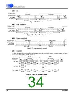
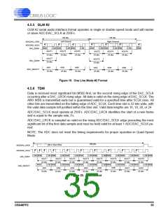
4.5.5 OLM #2
OLM #2 serial audio interface format operates in single or double-speed mode and will master
or slave ADC/DAC_SCLK at 256Fs.
128 clks
128 clks
Left Channel
Right Channel
ADC/DAC_LRCK
ADC/DAC_SCLK
DAC_SDIN1
MSB
AOUT1
LSB MSB
LSB MSB
LSB
MSB
LSB MSB
LSB MSB
LSB
MSB
AOUT3
24 clks
AOUT5
24 clks
AOUT2
24 clks
AOUT4
24 clks
AOUT6
24 clks
24 clks
AOUT7
24 clks
AOUT8
24 clks
DAC_SDIN4
AIN1
AIN3
AIN5
AIN2
AIN4
AIN6
ADC_SDOUT1
24 clks
24 clks
24 clks
24 clks
24 clks
24 clks
Figure 19. One Line Mode #2 Format
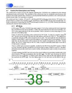
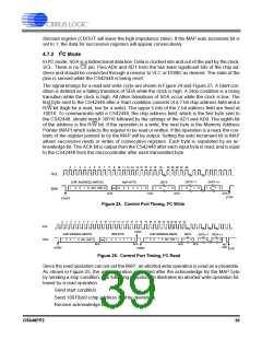
4.5.6 TDM
Data is received most significant bit (MSB) first, on the second rising edge of the DAC_SCLK
occurring after a DAC_LRCK rising edge. All data is valid on the rising edge of DAC_SCLK. The
AIN1 MSB is transmitted early but is guaranteed valid for a specified time after SCLK rises. All
other bits are transmitted on the falling edge of ADC_SCLK. Each time slot is 32 bits wide, with
the valid data sample left justified within the time slot. Valid data lengths are 16, 18, 20, or 24.
ADC/DAC_SCLK must operate at 256Fs. ADC/DAC_LRCK identifies the start of a new frame
and is equal to the sample rate, Fs.
ADC/DAC_LRCK is sampled as valid on the rising ADC/DAC_SCLK edge preceding the most
significant bit of the first data sample and must be held valid for at least 1 ADC/DAC_SCLK pe-
riod.
NOTE: The ADC does not meet the timing requirements for proper operation in Quad-Speed
Mode.
256 clks
Bit or Word Wide
ADC/DAC_LRCK
ADC/DAC_SCLK
DAC_SDIN1
LSB MSB
MSB
LSB MSB
LSB MSB
LSB MSB
AOUT2
LSB MSB
AOUT3
LSB MSB
LSB MSB
LSB MSB
LSB MSB
LSB MSB
LSB MSB
LSB MSB
LSB MSB
LSB MSB
LSB MSB
AOUT1
32 clks
AOUT4
32 clks
AOUT5
32 clks
AOUT6
32 clks
AOUT7
32 clks
AOUT8
32 clks
32 clks
32 clks
LSB MSB
LSB MSB
ADC_SDOUT1
AIN1
AIN2
AIN3
AIN4
AIN5
AIN6
AUX1
AUX2
32 clks
32 clks
32 clks
32 clks
32 clks
32 clks
32 clks
32 clks
Figure 20. TDM Format
DS648PP2
35

 CIRRUS [ CIRRUS LOGIC ]