CS42416
4.5.3
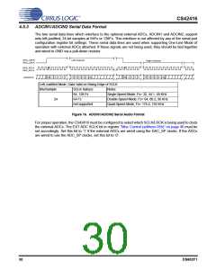
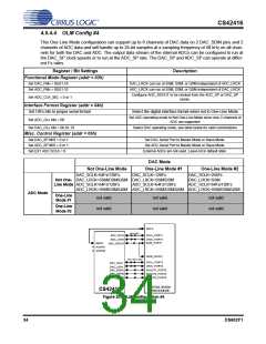
ADCIN1/ADCIN2 Serial Data Format
The two serial data lines which interface to the optional external ADCs, ADCIN1 and ADCIN2, support
only left-justified, 24-bit samples at 64Fs or 128Fs. This interface is not affected by any of the serial port
configuration register bit settings. These serial data lines are used when supporting One-Line Mode of
operation with external ADCs attached. If these signals are not being used, they should be tied together
and wired to GND via a pull-down resistor.
DAC_LRCK
ADC_LRCK
Left Channel
Right Channel
DAC_SCLK
ADC_SCLK
MSB
LSB
MSB
LSB
+5 +4 +3 +2 +1
+5 +4 +3 +2 +1
-1 -2 -3 -4 -5
-1 -2 -3 -4
ADCIN1/2
Left-Justified Mode, Data Valid on Rising Edge of SCLK
Bits/Sample
SCLK Rate(s)
64, 128 Fs
64 Fs
Notes
Single-Speed Mode, Fs= 32, 44.1, 48 KHz
Double-Speed Mode, Fs= 64, 88.2, 96 KHz
Quad-Speed Mode, Fs= 176.4, 192 KHz
24
not supported
Figure 16. ADCIN1/ADCIN2 Serial Audio Format
For proper operation, the CS42416 must be configured to select which SCLK/LRCK is being used to clock
the external ADCs. The EXT ADC SCLK bit in register “Misc Control (address 05h)” on page 46 must be
set accordingly. Set this bit to ‘1’ if the external ADCs are wired using the DAC_SP clocks. If the ADCs
are wired to use the ADC_SP clocks, set this bit to ‘0’.
30
DS602F1

 CIRRUS [ CIRRUS LOGIC ]