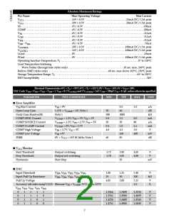
Electrical Characteristics: 0°C < TA < +70°C; 0°C < TJ < +125°C; 8V < VCC1 < 14V; 5V < VCC2 < 20V;
DAC Code: VID4 = VID2 = VID1 = VID0 = 1; VID3 = 0; CVGATE(L) and CVGATE(H) = 1nF; COFF = 330pF; CSS = 0.1µF, unless otherwise specified.
PARAMETER
ꢀ Soft Start (SS)
TEST CONDITIONS
MIN
TYP
MAX
UNIT
Charge Time
1.6
25
3.3
5.0
200
6.0
1.10
1.1
3.0
ms
ms
%
Pulse Period
100
3.3
Duty Cycle
(Charge Time/Pulse Period) × 100
VFB = 0V; VSS = 0
1.0
0.50
0.9
COMP Clamp Voltage
VFFB SS Fault Disable
High Threshold
0.95
1.0
V
VGATE(H) = Low; VGATE(L) = Low
V
2.5
V
ꢀ PWM Comparator
Transient Response
VFFB = 0 to 5V to VGATE(H) = 9V to 1V;
VCC1 = VCC2 = 12V
100
0.3
125
ns
VFFB Bias Current
VFFB = 0V
µA
ꢀ Supply Current
ICC1
No Switching
8.5
1.6
8
13.5
3.0
13
mA
mA
mA
mA
ICC2
No Switching
Operating ICC1
Operating ICC2
VFB = COMP = VFFB
VFB = COMP = VFFB
2
5
ꢀ COFF
Normal Charge Time
Extension Charge Time
Discharge Current
VFFB = 1.5V; VSS = 5V
VSS = VFFB = 0
1.0
5.0
5.0
1.6
8.0
2.2
µs
µs
11.0
COFF to 5V; VFB >1V
mA
ꢀ Time Out Timer
Time Out Time
V
FB = VCOMP; VFFB = 2V;
10
35
30
50
65
70
µs
%
Record VGATE(H) Pulse High Duration
Fault Mode Duty Cycle
VFFB = 0V
Note 1: Guaranteed by design, not 100% tested in production.
Package Pin Description
PACKAGE PIN #
PIN SYMBOL
FUNCTION
16L SO Narrow
1,2,3,4,6
VID0 – VID4
Voltage ID DAC input pins. These pins are internally pulled up to 5V
providing logic ones if left open. VID4 selects the DAC range. When VID4
is High (logic one), the DAC range is 2.14V to 3.54V with 100mV incre-
ments. When VID4 is Low (logic zero), the DAC range is 1.34V to 2.09V
with 50mV increments. VID0 - VID4 select the desired DAC output volt-
age. Leaving all 5 DAC input pins open results in a DAC output voltage
of 1.244V, allowing for adjustable output voltage, using a traditional
resistor divider.
5
SS
Soft Start Pin. A capacitor from this pin to LGnd in conjunction with
internal 60µA current source provides soft start function for the con-
troller. This pin disables fault detect function during Soft Start. When a
fault is detected, the soft start capacitor is slowly discharged by internal
2µA current source setting the time out before trying to restart the IC.
Charge/discharge current ratio of 30 sets the duty cycle for the IC when
the regulator output is shorted.
4

 CHERRY [ CHERRY SEMICONDUCTOR CORPORATION ]