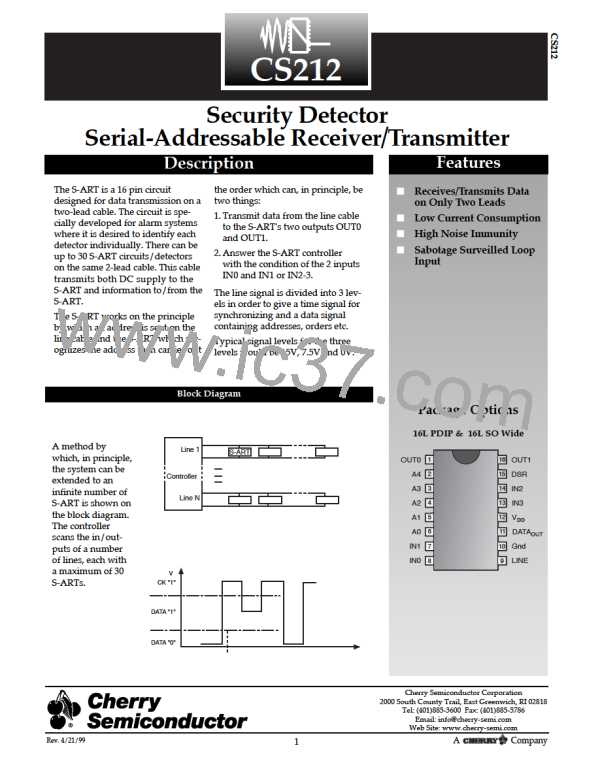
Absolute Maximum Ratings
Lead Temperature Soldering:
Wave Solder (through hole styles only) . . . . . . . . . . . . . . . . . . . . . . . . . . . . . . . . . . . . . . . . . . . .10 Sec. max 260ûC Peak
Reflow (SMD styles only) . . . . . . . . . . . . . . . . . . . . . . . . . . . . . . . . . . . . . . . . . . . .60 Sec max. above 183ûC, 230ûC Peak
Storage Temperature Range, TS . . . . . . . . . . . . . . . . . . . . . . . . . . . . . . . . . . . . . . . . . . . . . . . . . . . . . . . . . . . . . . . .-65 to 150ûC
Maximum Operating Junction Temperature, TJ . . . . . . . . . . . . . . . . . . . . . . . . . . . . . . . . . . . . . . . . . . . . . . . . . . . . . . . .125¡C
Electrical Characteristics: TA = 25¡C, unless otherwise specified.
PARAMETER
TEST CONDITIONS
MIN
TYP
MAX
UNIT
Operating Temperature Range, TA
-40
85
¡C
Device Current IDD
Not Addressed
Outputs unloaded
Line Voltage=0-15V, VDD=15V
0.47
3.55
0.80
mA
Device Current IDD
Power-Up-Mode
(5 corr. addr. bits)CP4-CP5
IN0, IN1 are Open
IN2, IN3 are Active
VDD=15V
5.50
9.64
2.86
1.2
mA
mA
mA
Device Current IDD
Addressed, Line Output
Transistor Active
IN2, IN3 not Active
IN0, IN1 are Open
VDD=15V
6.24
1.84
Device Current IDD
Addressed (4 corr.addr.bits)
Line Output Transistor Not Active
IN2, IN3 not Active
IN0, IN1 are Open
VDD=15V
Output Voltage Low Level
Out0, Out1, DSR
VDD=10-15V
ISINK=1mA
V
mA
V
Output sink Current
Out0, Out1, DSR
1.0
Output Voltage High Level
Out0, Out1, DSR
14
30
Leakage Current
Out0, Out1, DSR
VOUT=14V
µA
Input Voltage Level
Low
VDD=10-15V
VDD=10-15V
30%VDD
850
V
V
A0-A4, IN0, IN1
High
70%VDD
150
Input Current IN0, IN1=Gnd
Power-Up Mode
VDD=18V
µA
(4 corr.addr.bits)
Input Current
A0-A4, IN0, IN1
Not Addressed
VDD=18V
20
µA
Positive Trigger
Threshold
Voltage Vdd=15V
VP, C
VP, D
Clock Comparator
Data Comparator
11.0
4.6
11.7
5.7
12.4
6.6
V
V
Negative Trigger
Threshold Voltage
VNC
VNC
VDD=15V Clock Comparator
VDD=15V, Data Comparator
10.2
3.4
10.9
4.3
11.6
5.2
V
V
Hysteresis Voltage
Clock/Data Comp.
VDD=15V
0.7
0.8
V
Saturation Voltage For
Line Output Driver
VDD=15V, IC=50mA
VDD=15V, IC=10mA
VLINE=0-18V, VDD=18V
VDD=15V±1V
1
V
Saturation Voltage For
Line Output Driver
0.4
±16
V
Leakage Current
For the Line Output
µA
Line Signal Freq.
0
20
kHz
µs
Rise/Fall-Time Line Signal
0.25
250.00
2

 CHERRY [ CHERRY SEMICONDUCTOR CORPORATION ]