|
8
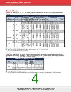
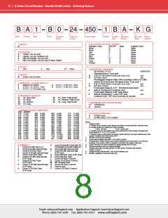
B-Series Circuit Breaker - Handle UL489 Listed – Ordering Scheme
B A 1 B 0 24 450 1 B A K G
8
9
10
Mounting/
Barriers
11
12
1
2
3
4
5
6
7
Terminal
Actuator
Color
Max. Appl. Agency
Rating
Series
Actuator
Poles
Circuit
Aux/Alarm
Switch
Frequency
& Delay
Current Rating
Approval
6
9 ACTUATOR COLOR & LEGEND
1 SERIES
Actuator Color
White
ON-OFF
Dual
Legend Color
Black
B
B
D
G
J
1
2
3
4
5
6
7
8
Black
White
1
2 ACTUATOR
Red
White
A
B
S
T
Handle, one per pole
Green
Blue
Yellow
Gray
White
Handle, one per multipole unit
Mid-Trip Handle, one per pole
L
White
N
Q
S
Black
Mid-Trip Handle, one per pole & Alarm Switch
Black
Orange
Black
2
3 POLES
One
3
1
2
Two
3
Three
10 MOUNTING / BARRIERS
MOUNTING STYLE
BARRIERS
Threaded Insert, 2 per pole
4 CIRCUIT
Series Trip (Current)
A
B
6-32 x 0.195 inches (multi-pole units only)
yes
yes
B
ISO M3 x 5mm
Rectangular Adapter Plate with mounting centers of 2.062
7
inches [52.37mm] and Threaded insert, 2 per pole
4
5 AUXILIARY / ALARM SWITCH
C
D
6-32 X 0.225 inches (multi-pole units only)
ISO M3 x 6.5mm
yes
yes
0
2
3
without Aux Switch
8
9
S.P.S.T., 0.187 Q.C. Term.
S.P.D.T., 0.187 Q.C. Term.
S.P.D.T., 0.110 Q.C. Term.
S.P.D.T., 0.110 Solder Lug
Front panel Snap-In, 0.75” [19.05mm] wide bezel
without Handleguard (multipole only)
Front panel Snap-In, 0.96” wide bezel
without Handleguard, 1-pole 0.96” wide;
(multipole only) .105” bezel overhang on all sides
6
8
yes
yes
6 FREQUENCY & DELAY
21
22
24
26
AC Ultra Short
AC Short
AC Medium
AC Long
42
44
46
AC, Short, High-inrush
AC, Medium, High-inrush
AC, Long, High-inrush
11 MAXIMUM APPLICATION RATING
8
C
K
120/240VAC
120VAC
7 CURRENT RATING (AMPERES)
CODE AMPERES
12 AGENCY APPROVAL
210 0.100
215 0.150
220 0.200
225 0.250
230 0.300
235 0.350
240 0.400
245 0.450
250 0.500
255 0.550
260 0.600
265 0.650
270 0.700
275 0.750
280 0.800
285 0.850
290 0.900
295 0.950
410 1.000
512 1.250
415 1.500
517 1.750
420 2.000
522 2.250
527 2.750
430 3.000
435 3.500
440 4.000
445 4.500
450 5.000
455 5.500
460 6.000
465 6.500
470 7.000
475 7.500
480 8.000
485 8.500
490 9.000
495 9.500
610 10.000
710 10.500
611 11.000
711 11.500
612 12.000
712 12.500
613 13.000
614 14.000
615 15.000
616 16.000
617 17.000
618 18.000
620 20.000
622 22.000
624 24.000
625 25.000
630 30.000
G
3
UL489 Listed
UL489 Listed, TUV Certified
Notes:
1
Actuator Code:
A: Handle tie pin spacer(s) and retainers provided un-assembled with multi-pole units.
B: Handle location as viewed from front of breaker:
2 pole - left pole
3 pole - center pole
S: Handle moves to mid-position only upon electrical trip of the breaker. Available with
circuit codes B, C, D, E, F, G, H and K.
T: Handle moves to mid-position and alarm switch activates only upon electrical trip of the
breaker. Available with circuit codes B & C.
2
3
4
All poles must be same polarity.
3 pole units available only when 1 of 3 poles is neutral.
Auxiliary/Alarm Switch circuit must be same polarity as the main circuit. On multi-pole
breakers, one auxiliary switch is supplied, mounted in the extreme right pole.
Screw Terminals are recommended on ratings greater than 20 amps.
Standard actuator colors are black and white.
5
6
7
4
8 TERMINAL
A
Load Terminal #8 Screw with QC
Combination (Special Catalog #)
Screw M5 with upturned lugs
Screw M5 with upturned lugs
& 30° bend
1
2
3
4
5
6
Push-On 0.250 Tab (Q.C.)
Screw 8-32 with upturned lugs
Screw 8-32 (Bus Type)
Screw 10-32 with upturned lugs
Screw 10-32 (Bus Type)
Screw 8-32 with upturned lugs
& 30° bend
Adapter plate with mounting centers of 2.082 inches. Available with Actuator
Codes A, S and T.
Voltage Rating available with 2 and 3-pole breakers only.
Barriers supplied on multi-pole units only.
B
F
8
9
G
H
J
K
M
N
Q
Y
Screw M5 (Bus Type) & 30° bend
Screw M5 (Bus Type)
Screw M5 Back Connect
Screw 10-32 Back Connect
M6 Threaded Stud
7
8
9
Screw 8-32 (Bus Type)
& 30° bend
Screw 10-32 with upturned lugs
& 30° bend
Screw 10-32 (Bus Type)
& 30° bend
Screw M4 Back Connect
Push-In Stud
Screw 8-32 Back Connect
Email: sales@carlingtech.com Application Support: team2@carlingtech.com
Phone: (860) 793–9281 Fax: (860) 793–9231 www.carlingtech.com

 Carling Technologies [ Carling Technologies ]