Features
■ Stable, infinite resolution cermet element
■ Vertical and horizontal adjust styles
■ Optional packaging on embossed tape
■ Compatible with surface mount
manufacturing processes
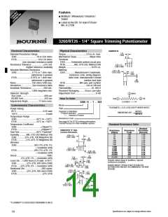
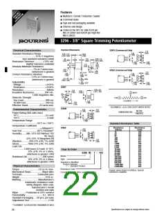
3269 - 1/4” Square SMD Trimming Potentiometer
3269P
Common Dimensions
Electrical Characteristics
WIPER
2
.51
(.020)
.51
(.020)
1.78
(.070)
Standard Resistance Range
ADJ. SLOT
DIA.
WIDE
X
X
DEEP
....................................10 to 1 megohm
(see standard resistance table)
Resistance Tolerance .............±10% std.
(closer tolerance available)
CW
CCW
3
1
1.02
(.040)
6.35 ± .51
(.250 ± .020)
CLOCKWISE
1.02
(.040)
TOLERANCES: ± 0.25 (.010) EXCEPT WHERE NOTED
Absolute Minimum Resistance
...............................1% or 2 ohms max.
(whichever is greater)
Contact Resistance Variation
............................3.0% or 3 ohms max.
(whichever is greater)
TYP
3 PLCS.
5.21
(.205)
METRIC
(INCHES)
DIMENSIONS ARE:
2.54
(.015)
TYP. 3 PLCS.
2
3
1
How To Order
1.52 ± .38
(.060 ± .015)
2.54
(.100)
3269 X - 1 - 103 G
Adjustability
Model
2.54
(.100)
Voltage ......................................±0.02%
Resistance ................................±0.05%
Resolution.....................................Infinite
Insulation Resistance ................500 vdc.
1,000 megohms min.
.46 ± .03
(.018 ± .001)
DIA. TYP.
Style
Standard Product
Resistance Code
3269W
.43 ± .05
(.017 ± .002)
DIA. TYP.
Optional Suffix Letter
G= Embossed Tape
Dielectric Strength
3
1
“P” Style - 750 pcs./13˝ reel
“W, X” Style - 500 pcs./13˝ reel
Sea Level ..................................600 vac
80,000 Feet...............................250 vac
Effective Travel..................12 turns nom.
1.52 ± .38
(.060 ± .015)
2
1.02
(.040)
Environmental Characteristics
4.32
(.170)
Maximum Exposure (Temp/Time)
.................................... +245°C/10 sec.
Power Rating (300 volts max.)
6.35 ± .51
(.250 ± .020)
SQ.
Standard Resistance Table
1.02
(.040)
1.02
Resistance
(Ohms)
10
20
50
Resistance
Code
85°C .......................................0.25 watt
150°C ..........................................0 watt
Temperature Range ......-65°C to +150°C
Temperature Coefficient .....±100ppm/°C
Seal Test ........................85°C Fluorinert*
Humidity........MIL-STD-202 Method 106
(2% ∆TR; IR 100 Megohms)
Vibration............30G (1% ∆TR; 1% ∆VR)
Shock..............100G (1% ∆TR; 1% ∆VR)
Load Life...1,000 hours 0.25 watt @ 85°C
(3% ∆TR; 3% or 3 ohms
(.040)
TYP
7.37
(.290)
100
200
500
100
101
201
501
102
202
502
103
203
253
503
104
2.54
(.015)
2.54
(.100)
2.54
(.100)
TYP.
200
3 PLCS.
500
1,000
2,000
5,000
10,000
20,000
25,000
50,000
100,000
3269X
1.52 ± .38
(.060 ± .015)
1.02
(.040)
whichever is greater, CRV)
Rotational Life ........................200 cycles
(2% ∆TR; 3% or 3 ohms,
1.02
(.040)
200,000
250,000
500,000
1,000,000
204
254
504
105
7.37
(.290)
whichever is greater, CRV)
Physical Characteristics
SHADED AREAS TYPICALLY NOT STOCKED BY
DISTRIBUTORS AND NOT RECOMMENDED FOR NEW
DESIGNS.
2
2.29
(.090)
Torque .............................3.0 oz-in. max.
Mechanical Stops..................Wiper idles
Terminals ........................Solderable pins
Weight ......................................0.015 oz.
Marking ...........................Manufacturer’s
trademark, resistance code,
TYP.
3 PLCS.
3
1
RECOMMENDED PCB
LAYOUT - "P"
wiring diagram, date code,
RECOMMENDED PCB
LAYOUT - "W" & "X"
manufacturer’s model
1.19
TYP.
number and style
Standard Packaging .....50 pcs. per tube
Adjustment Tool ..............................H-90
(.047)
9.70
2.79
(.382)
(.110)
TYP.
2.54
7.62
(.100)
(.300)
2.54
(.100)
*”FLUORINERT” IS A REGISTERED TRADEMARK OF 3M CO.
3.30
(.130)
TYP.
2.54
2.54
1.19
TYP.
(.100)
(.100)
(.047)
Specifications are subject to change without notice.
22

 BOURNS [ BOURNS ELECTRONIC SOLUTIONS ]