Industrial Environment
DC-DC Converters >100Watt
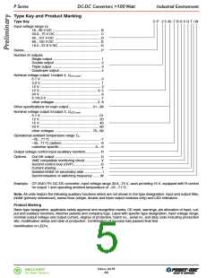
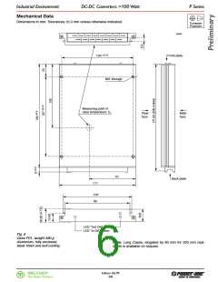
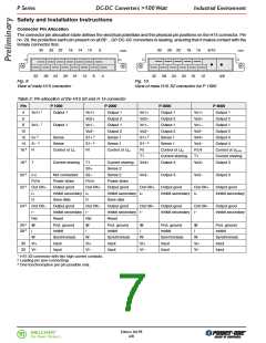
P Series
Installation Instruction
The P series DC-DC converters are components, intended
exclusively for inclusion within other equipment by an in-
dustrial assembly operation or by professional installers.
Installation must strictly follow the national safety regula-
tions in compliance with the enclosure, mounting, creep-
age, clearance, casualty, markings and segregation re-
quirements of the end-use application. See also: Technical
Information: Installation and Application.
Cleaning Agents
In order to avoid possible damage, any penetration of
cleaning fluids is to be prevented, since the power supplies
are not hermetically sealed.
Standards and approvals
All P series DC-DC converters correspond to class I equip-
ment.
Connection to the system shall be made via the female
connector H15 or H15 S2 (see: Accessories) according to
Connector pin allocation. Other installation methods may
not meet the safety requirements.
They are pending to be UL recognized according to UL
1950, UL recognized for Canada to CAN/CSA C22.2 No.
950-95 and LGA approved to IEC/EN 60950 standards and
have been designed in accordance with these standards
for:
Check for hazardous voltages before altering any connec-
tions.
• Building in
• Basic insulation between input and case, based on
250 V AC or 240 V DC
• Double or reinforced insulation between input and out-
put, based on 250 V AC or 240 V DC
The DC-DC converters are provided with pin no. 26 ( ),
which is reliably connected to the case. For safety reasons
it is essential to connect these pins to the protective earth of
the supply system if required in: Safety of operator accessi-
ble output circuit.
• Operational insulation between output(s) and case
• Operational insulation between the outputs
• Operational insulation between option D or i and out-
put(s)
• Operational insulation between option D or i and case
• The use in a pollution degree 2 environment
• Connecting the input to a primary circuit with a maximum
transient rating of 2500 V (overvoltage class III based on
a 110 V primary circuit, overvoltage class II based on a
230 V primary circuit).
The Vi input (pin no. 32) is internally fused. This fuse is de-
signed to protect the unit in case of overcurrent and may
not be able to satisfy all customer requirements. External
fuses in the wiring to one or both input pins (no. 30 and/or
no. 32) may therefore be necessary to ensure compliance
with local requirements.
Important: Whenever the inhibit function is not in use,
pin 28 (i) should be connected to pin 32 (Vi–) to enable
the output(s).
After approvals, the AC-DC converters are subject to
manufacturing surveillance in accordance with the above
mentioned UL, CSA, EN and with ISO 9001 standards.
Do not open the modules, or guarantee will be invalidated.
Make sure that there is sufficient air flow available for con-
vection cooling. This should be verified by measuring the
case temperature when the unit is installed and operated in
the end-use application. The maximum specified case tem-
perature TC max must not be overridden.
Protection Degree
Condition: Female connector fitted to the unit.
The protection degree of the DC-DC converters is IP 40.
Ensure that a unit failure (e.g. by an internal short-circuit)
does not result in a hazardous condition. See also: Safety
of operator accessible output circuit.
Isolation
The electric strength test is performed as factory test in accordance with IEC/EN 60950 and UL 1950 and should not be
repeated in the field. Melcher will not honour any guarantee claims resulting from electric strength field tests.
Table 3: Isolation
Characteristic
Input to
case
Input to Output to Output to Auxiliary 1 Auxiliary 1 Auxiliary 1 Unit
output(s)
case
output(s) to input
to case to output
Electric
strength
test voltage
Required according to
IEC/EN 60950
1.5
2.1
2.1
1.5
3.0 2
0.5
-
-
3.0 2
4.2 2
4.2 2
3.0 2
0.5
0.7
1.5
1.1
0.5
0.7
kVrms
4.2 2
0.7
kV DC
Actual factory test 1 s
4.2 2
1.5
0.5
0.35
0.5
AC test voltage equivalent
to actual factory test
3.0 2
1.1
0.35
kVrms
Insulation resistance at 500 V DC
>300
>300
>300
>100
>300
>100
>100
MΩ
1 Insulated auxiliary circuits, e.g. Out OK output circuit (option D), inhibit on output side (option i).
2 In accordance with IEC/EN 60950 only subassemblies are tested in factory with this voltage.
Edition 4/6.99
MELCHER
7/8
The Power Partners.

 BEL [ BEL FUSE INC. ]