Data Sheet
CURRENT MODE PWM CONTROLLER
AP384XC
ELectrical Characteristics (Continued)
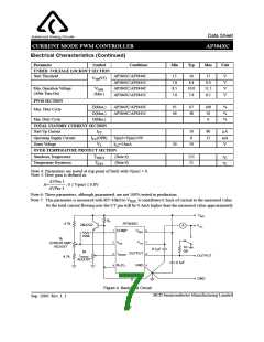
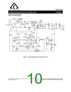
Figure 4 is the basic test circuit for AP384XC. In testing, the high peak currents associated with capacitive loads
necessitate careful grounding techniques. Timing and bypass capacitors should be connected close to pin 5 in a
single point ground. The transistor and 5k potentiometer are used to sample the oscillator waveform and apply an
adjustable ramp to pin 3.
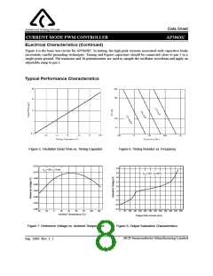
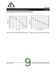
Typical Performance Characteristics
Figure 5. Oscillator Dead Time vs. Timing Capacitor
Figure 6. Timing Resistor vs. Frequency
5.015
4.0
3.5
3.0
2.5
2.0
1.5
1.0
0.5
0.0
-0.5
VCC=15V, IO=1mA
5.010
VCC=15V, TA=25oC
5.005
5.000
4.995
4.990
4.985
4.980
-40
-20
0
20
40
60
80
100
120
0
50 100 150 200 250 300 350 400 450 500 550 600
Output Sink Current (mA)
Ambient Temperature (oC)
Figure 7. Reference Voltage vs. Ambient Temperature
Figure 8. Output Saturation Characteristics
BCD Semiconductor Manufacturing Limited
Sep. 2006 Rev. 1. 1
8

 BCDSEMI [ BCD SEMICONDUCTOR MANUFACTURING LIMITED ]