Data Sheet
WHITE LED STEP-UP CONVERTER
AP3019A
Application Information
Over Voltage Protection
Operation
The AP3019A has an internal open-circuit protection
circuit. When the LEDs are disconnected from circuit
or fail open, the output voltage is clamped. The
AP3019A will switch at a low frequency, and
minimize input current.
The AP3019A is a boost DC-DC converter which
uses a constant frequency, current mode control
scheme to provide excellent line and load regulation.
Operation can be best understood by referring to the
Figure 3.
At the start of each oscillator cycle, the SR latch is set
and switch Q1 turns on. The switch current will
increase linearly. The voltage on sense resistor is
proportional to the switch current. The output of the
current sense amplifier is added to a stabilizing ramp
and the result is fed into the non-inversion input of
the PWM comparator A2. When this voltage exceeds
the output voltage level of the error amplifier A1, the
SR latch is reset and the switch is turned off.
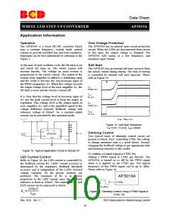
Soft Start
The AP3019A has an internal soft start circuit to limit
the inrush current during startup. The time of startup
is controlled by internal soft start capacitor. Please
refer to Figure 19.
IIN
100mA/div
VOUT
It is clear that the voltage level at inversion input of
A2 sets the peak current level to keep the output in
regulation. This voltage level is the output signal of
error amplifier A1, and is the amplified signal of the
voltage difference between feedback voltage and
reference voltage of 200mV. So, a constant output
current can be provided by this operation mode.
5V/div
VFB
100mV/div
VCTRL
2V/div
Time 100µs/div
Figure 19. Soft Start Waveform
VIN=3.6V, 5 LEDs, ILED=20mA
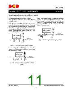
Dimming Control
Two typical types of dimming control circuit are
present as below. First, controlling CTRL Pin voltage
to change operation state is a good choice. Second,
changing the feedback voltage to get appropriate duty
and luminous intensity is also useful.
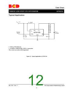
Figure 18. Typical Application Circuit to Decide R1
(1) Adding a Control Signal to CTRL Pin
Adding a PWM Signal to CTRL pin directly. The
AP3019A is turned on or off by the PWM signal
when it is applied on the CTRL pin. The typical
frequency of this PWM signal can be up to 2kHz.
Please refer to Figure 20.
LED Current Control
Refer to Figure 18, the LED current is controlled by
the feedback resistor R1. LEDs' current accuracy is
determined by the regulator's feedback threshold
accuracy and is independent of the LED's forward
voltage variation. So the precise resistors are
preferred. The resistance of R1 is in inverse
proportion to the LED current since the feedback
reference is fixed at 200mV. The relation for R1 and
LED current can be expressed as below:
AP3019A
CTRL
up to 2kHz
200mV
R1 =
Figure 20. Dimming Control Using a PWM Signal in
CTRL Pin
ILED
Mar. 2010 Rev. 1.7
BCD Semiconductor Manufacturing Limited
10

 BCDSEMI [ BCD SEMICONDUCTOR MANUFACTURING LIMITED ]