Data Sheet
PRIMARY SIDE CONTROL IC FOR OFF-LINE BATTERY CHARGERS AP3706
Operation Description
Bridge
Vg
VS
VO
D1
VIN
+
IS
+
C1
CO
IO
NP
NS
LM
VAUX
NAUX
Q1
OUT
AP3706
IP
FB
GND
CS
RCS
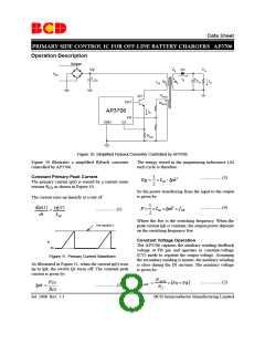
Figure 10. Simplified Flyback Converter Controlled by AP3706
Figure 10 illustrates a simplified flyback converter
controlled by AP3706.
The energy stored in the magnetizing inductance LM
each cycle is therefore:
Constant Primary Peak Current
The primary current ip(t) is sensed by a current sense
1
................(3)
Eg = ×LM ⋅ Ipk2
2
resistor R as shown in Figure 10.
CS
So the power transferring from the input to the output
is given by:
The current rises up linearly at a rate of:
1
P = ×LM ×Ipk2 × fSW
dip(t) vg(t)
................(4)
................(1)
=
2
dt
LM
Where the fsw is the switching frequency. When the
peak current Ipk is constant, the output power depends
on the switching frequency fsw.
See equation 2
Constant Voltage Operation
Ip
The AP3706 captures the auxiliary winding feedback
voltage at FB pin and operates in constant-voltage
(CV) mode to regulate the output voltage. Assuming
the secondary winding is master, the auxiliary winding
is slave during the D1 on-time. The auxiliary voltage
is given by:
0A
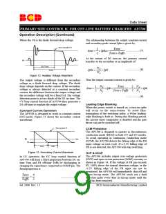
Figure 11. Primary Current Waveform
As illustrated in Figure 11, when the current ip(t) rises
up to Ipk, the switch Q1 turns off. The constant peak
current is given by:
NAUX
................(5)
Vcs
VAUX
=
×
(
Vo +Vd
)
................(2)
Ipk =
NS
Rcs
Jul. 2008 Rev. 1.3
BCD Semiconductor Manufacturing Limited
8

 BCDSEMI [ BCD SEMICONDUCTOR MANUFACTURING LIMITED ]