F/S Mode
S
0
0
0
0
1
X
X
X
N
HS Mode Master Code
HS Mode Enabled
ADC Power-Down Mode
ADC Sampling Mode
PD PD
Sr
1
0
0
1
0
A
A
W
A
SD
C
C
C
X
0
X
A
1
0
2
1
0
1
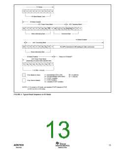
Write-Addressing Byte
Command Byte
HS Mode Enabled
ADC Converting Mode
SCLH(2) is stretched LOW waiting for data conversion
Sr
1
0
0
1
0
A
A
R
A
1
0
Read-Addressing Byte
Return to F/S Mode(1)
HS Mode Enabled
ADC Power-Down Mode
(depending on power-down selection bits)
D
D
D
D
D
D
D
D
0
N
P
7
6
5
4
3
2
1
1 x (8 Bits + not-ack)
A = acknowledge (SDA LOW)
N = not acknowledge (SDA HIGH)
S = START Condition
P = STOP Condition
Sr = repeated START condition
W = '0' (WRITE)
R = '1' (READ)
From Master to Slave
From Slave to Master
NOTES: (1) To remain in HS mode, use repeated START instead of STOP.
(2) SCLH is SCL in HS mode.
FIGURE 4. Typical Read Sequence in HS Mode.
ADS7830
13
www.ti.com
SBAS302

 BB [ BURR-BROWN CORPORATION ]