F95 Series
Standard Conformal Coated Chip
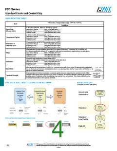
QUALIFICATION TABLE
F95 series (Temperature range -55ºC to +125ºC)
TEST
Condition
At 40°C, 90 to 95% R.H., 500 hours (No voltage applied)
Capacitance Change .................. Refer to the table above (*1)
Dissipation Factor ....................... Initial specified value or less
Leakage Current .......................... Initial specified value or less
Damp Heat
(Steady State)
At -55°C / +125°C, 30 minutes each, 5 cycles
Capacitance Change .................. Refer to the table above(*1)
Dissipation Factor ....................... Initial specified value or less
Leakage Current .......................... Initial specified value or less
Temperature Cycles
10 seconds reflow at 260°C, 10 seconds immersion at 260°C.
Capacitance Change .................. Refer to the table above (*1)
Dissipation Factor ....................... Initial specified value or less
Leakage Current .......................... Initial specified value or less
Resistance to
Soldering Heat
After application of surge voltage in series with a 33Ω resistor at the rate of 30 seconds ON, 30 seconds OFF,
for 1000 successive test cycles at 85ºC, capacitors shall meet the characteristic requirements in the table above.
Capacitance Change .................. Refer to the table above (*1)
Surge
Dissipation Factor ....................... Initial specified value or less
Leakage Current .......................... Initial specified value or less
After 2000 hours’ application of rated voltage at 85°C,
capacitors shall meet the characteristic requirements in the table above.
Capacitance Change ....................Refer to the table above (*1)
Dissipation Factor .........................Initial specified value or less
Leakage Current ...........................Initial specified value or less
Endurance
After applying the pressure load of 5N for 10±1 seconds horizontally to the center of capacitor side body which
has no electrode and has been soldered beforehand on a substrate, there shall be found neither exfoliation nor its
sign at the terminal electrode.
Shear Test
Keeping a capacitor surface-mounted on a substrate upside down and supporting the substrate at both of the
opposite bottom points 45mm apart from the center of capacitor, the pressure strength is applied with a specified
jig at the center of substrate so that the substrate may bend by 1mm as illustrated. Then, there shall be found no
remarkable abnormality on the capacitor terminals.
Terminal Strength
AVX SOLID ELECTROLYTIC CAPACITOR ROADMAP
SERIES LINE UP :
CONVENTIONAL SMD MnO2
The Important Information/Disclaimer is incorporated in the catalog where these specifications came from or
available online at www.avx.com/disclaimer/ by reference and should be reviewed in full before placing any order.
156
122920

 KYOCERA AVX [ KYOCERA AVX ]