AUSTIN SEMICONDUCTOR, INC.
FLASH
AS8FLC2M32
Austin Semiconductor, Inc.
If RESET\ is asserted during a PROGRAM or ERASE opera- identification, and sector protection verification through
tion, the RY/BY\ pin remains a “0” (busy) until the internal identifier codes output via the appropriate Byte DQ’s. This
reset operation is complete, which requires a time of tREADY. mode is primarily intended for programming equipment to
The system can thus monitor RY/BY\ to determine whether the automatically match a device to be programmed with its
RESET operation is complete. If RESET\ is asserted when a
corresponding programming algorithm. However, the
autoselect codes can also be accessed in-system through the
command register.
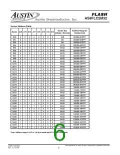
Autoselect Code Table
PROGRAM or ERASE operation is not executing (RY/BY\ pin
is “1”), the RESET operation is completed within a time of
tREADY. The system can read data tRH after the RESET\ pin
returns to VIH.
When using programming equipment (modified to support
multi-byte devices, or supplied from the programming
equipment provider as such), the autoselect mode requires
VID (11.5v to 12.5v) on address pinA9. Address pinsA6,A1,
and A0 must be as shown in the Autoselect Table below. In
addtion, when verifying sector protection, the sector address
must appear on the appropriate highest order address bits.
When all necessary bits have been set as required, the
programming equipment may then read the corresponding
identifier code on the appropriate Byte DQ’s.
Refer to the “AC Characteristics” tables for RESET\ parameters.
Output Disable Mode
When the OE\ input is at VIH, output from the device is disabled.
The output pins are placed in the high Impedance State.
Autoselect Mode
The autoselect mode provides manufacturer and device
To access the autoselect codes in-system, the host system
can issue the autoselect command via the command register.
Austin Semiconductor, Inc. reserves the right to change products or specifications without notice.
AS8FLC2M32B
Rev. 1.2 5/09
5

 AUSTIN [ AUSTIN SEMICONDUCTOR ]