ATmega64A
Output mode output is set on Compare Match and cleared at BOTTOM. Due to the single-slope
operation, the operating frequency of the fast PWM mode can be twice as high as the phase cor-
rect and phase and frequency correct PWM modes that use dual-slope operation. This high
frequency makes the fast PWM mode well suited for power regulation, rectification, and DAC
applications. High frequency allows physically small sized external components (coils, capaci-
tors), hence reduces total system cost.
The PWM resolution for fast PWM can be fixed to 8-, 9-, or 10-bit, or defined by either ICRn or
OCRnA. The minimum resolution allowed is 2-bit (ICRn or OCRnA set to 0x0003), and the max-
imum resolution is 16-bit (ICRn or OCRnA set to MAX). The PWM resolution in bits can be
calculated by using the following equation:
log(TOP + 1)
R
= ----------------------------------
FPWM
log(2)
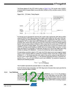
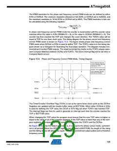
In fast PWM mode the counter is incremented until the counter value matches either one of the
fixed values 0x00FF, 0x01FF, or 0x03FF (WGMn3:0 = 5, 6, or 7), the value in ICRn (WGMn3:0 =
14), or the value in OCRnA (WGMn3:0 = 15). The counter is then cleared at the following timer
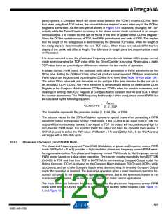
clock cycle. The timing diagram for the fast PWM mode is shown in Figure 15-7. The figure
shows fast PWM mode when OCRnA or ICRn is used to define TOP. The TCNTn value is in the
timing diagram shown as a histogram for illustrating the single-slope operation. The diagram
includes non-inverted and inverted PWM outputs. The small horizontal line marks on the TCNTn
slopes represent Compare Matches between OCRnx and TCNTn. The OCnx interrupt flag will
be set when a Compare Match occurs.
Figure 15-7. Fast PWM Mode, Timing Diagram
OCRnx / TOP Update
and TOVn Interrupt Flag
Set and OCnA Interrupt
Flag Set or ICFn
Interrupt Flag Set
(Interrupt on TOP)
TCNTn
(COMnx1:0 = 2)
OCnx
(COMnx1:0 = 3)
OCnx
1
2
3
4
5
6
7
8
Period
The Timer/Counter Overflow Flag (TOVn) is set each time the counter reaches TOP. In addition
the OCnA or ICFn flag is set at the same timer clock cycle as TOVn is set when either OCRnA or
ICRn is used for defining the TOP value. If one of the interrupts are enabled, the interrupt han-
dler routine can be used for updating the TOP and compare values.
When changing the TOP value the program must ensure that the new TOP value is higher or
equal to the value of all of the compare registers. If the TOP value is lower than any of the com-
pare registers, a Compare Match will never occur between the TCNTn and the OCRnx. Note
125
8160C–AVR–07/09

 ATMEL [ ATMEL ]