ATmega64A
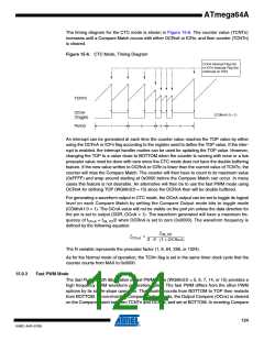
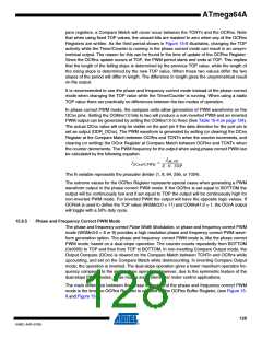
The timing diagram for the CTC mode is shown in Figure 15-6. The counter value (TCNTn)
increases until a Compare Match occurs with either OCRnA or ICRn, and then counter (TCNTn)
is cleared.
Figure 15-6. CTC Mode, Timing Diagram
OCnA Interrupt Flag Set
or ICFn Interrupt Flag Set
(Interrupt on TOP)
TCNTn
OCnA
(Toggle)
(COMnA1:0 = 1)
1
2
3
4
Period
An interrupt can be generated at each time the counter value reaches the TOP value by either
using the OCFnA or ICFn flag according to the register used to define the TOP value. If the inter-
rupt is enabled, the interrupt handler routine can be used for updating the TOP value. However,
changing the TOP to a value close to BOTTOM when the counter is running with none or a low
prescaler value must be done with care since the CTC mode does not have the double buffering
feature. If the new value written to OCRnA or ICRn is lower than the current value of TCNTn, the
counter will miss the Compare Match. The counter will then have to count to its maximum value
(0xFFFF) and wrap around starting at 0x0000 before the Compare Match can occur. In many
cases this feature is not desirable. An alternative will then be to use the fast PWM mode using
OCRnA for defining TOP (WGMn3:0 = 15) since the OCRnA then will be double buffered.
For generating a waveform output in CTC mode, the OCnA output can be set to toggle its logical
level on each Compare Match by setting the Compare Output mode bits to toggle mode
(COMnA1:0 = 1). The OCnA value will not be visible on the port pin unless the data direction for
the pin is set to output (DDR_OCnA = 1). The waveform generated will have a maximum fre-
quency of fOC A = fclk_I/O/2 when OCRnA is set to zero (0x0000). The waveform frequency is
n
defined by the following equation:
f
clk_I/O
f
= --------------------------------------------------
OCnA
2 ⋅ N ⋅ (1 + OCRnA)
The N variable represents the prescaler factor (1, 8, 64, 256, or 1024).
As for the Normal mode of operation, the TOVn flag is set in the same timer clock cycle that the
counter counts from MAX to 0x0000.
15.9.3
Fast PWM Mode
The fast Pulse Width Modulation or fast PWM mode (WGMn3:0 = 5, 6, 7, 14, or 15) provides a
high frequency PWM waveform generation option. The fast PWM differs from the other PWM
options by its single-slope operation. The counter counts from BOTTOM to TOP then restarts
from BOTTOM. In non-inverting Compare Output mode, the Output Compare (OCnx) is cleared
on the Compare Match between TCNTn and OCRnx, and set at BOTTOM. In inverting Compare
124
8160C–AVR–07/09

 ATMEL [ ATMEL ]