ATmega64A
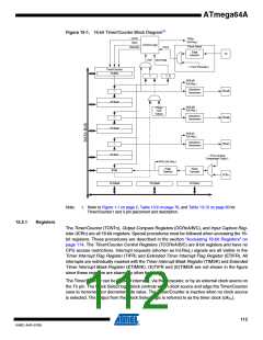
The double buffered Output Compare Registers (OCRnA/B/C) are compared with the
Timer/Counter value at all time. The result of the compare can be used by the Waveform Gener-
ator to generate a PWM or variable frequency output on the Output Compare Pin (OCnA/B/C).
See “Output Compare Units” on page 120. The Compare Match event will also set the Compare
Match Flag (OCFnA/B/C) which can be used to generate an Output Compare interrupt request.
The Input Capture Register can capture the Timer/Counter value at a given external (edge trig-
gered) event on either the Input Capture pin (ICPn) or on the Analog Comparator pins (See
“Analog Comparator” on page 230.) The Input Capture unit includes a digital filtering unit (Noise
Canceler) for reducing the chance of capturing noise spikes.
The TOP value, or maximum Timer/Counter value, can in some modes of operation be defined
by either the OCRnA Register, the ICRn Register, or by a set of fixed values. When using
OCRnA as TOP value in a PWM mode, the OCRnA Register can not be used for generating a
PWM output. However, the TOP value will in this case be double buffered allowing the TOP
value to be changed in run time. If a fixed TOP value is required, the ICRn Register can be used
as an alternative, freeing the OCRnA to be used as PWM output.
15.2.2
Definitions
The following definitions are used extensively throughout this section:
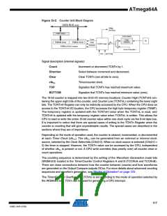
Table 15-1. Definitions
BOTTOM
MAX
The counter reaches the BOTTOM when it becomes 0x0000.
The counter reaches its MAXimum when it becomes 0xFFFF (decimal 65535).
TOP
The counter reaches the TOP when it becomes equal to the highest value in the
count sequence. The TOP value can be assigned to be one of the fixed values:
0x00FF, 0x01FF, or 0x03FF, or to the value stored in the OCRnA or ICRn Reg-
ister. The assignment is dependent of the mode of operation.
15.2.3
Compatibility
The 16-bit Timer/Counter has been updated and improved from previous versions of the 16-bit
AVR Timer/Counter. This 16-bit Timer/Counter is fully compatible with the earlier version
regarding:
• All 16-bit Timer/Counter related I/O Register address locations, including Timer Interrupt
Registers.
• Bit locations inside all 16-bit Timer/Counter registers, including Timer Interrupt Registers.
• Interrupt Vectors.
The following control bits have changed name, but have same functionality and register location:
• PWMn0 is changed to WGMn0.
• PWMn1 is changed to WGMn1.
• CTCn is changed to WGMn2.
The following registers are added to the 16-bit Timer/Counter:
• Timer/Counter Control Register C (TCCRnC).
• Output Compare Register C, OCRnCH and OCRnCL, combined OCRnC.
The following bits are added to the 16-bit Timer/Counter control registers:
• COM1C1:0 are added to TCCR1A.
113
8160C–AVR–07/09

 ATMEL [ ATMEL ]