ATmega64A
15. 16-bit Timer/Counter (Timer/Counter1 and Timer/Counter3)
15.1 Features
• True 16-bit Design (i.e., Allows 16-bit PWM)
• Three Independent Output Compare Units
• Double Buffered Output Compare Registers
• One Input Capture Unit
• Input Capture Noise Canceler
• Clear Timer on Compare Match (Auto Reload)
• Glitch-free, Phase Correct Pulse Width Modulator (PWM)
• Variable PWM Period
• Frequency Generator
• External Event Counter
• Ten Independent Interrupt Sources (TOV1, OCF1A, OCF1B, OCF1C, ICF1, TOV3, OCF3A, OCF3B,
OCF3C, and ICF3)
15.1.1
Restrictions in ATmega103 Compatibility Mode
Note that in ATmega103 compatibility mode, only one 16-bit Timer/Counter is available
(Timer/Counter1). Also note that in ATmega103 compatibility mode, the Timer/Counter1 has two
compare registers (Compare A and Compare B) only.
15.2 Overview
The 16-bit Timer/Counter unit allows accurate program execution timing (event management),
wave generation, and signal timing measurement. Most register and bit references in this
datasheet are written in general form. A lower case “n” replaces the Timer/Counter number, and
a lower case “x” replaces the Output Compare unit channel. However, when using the register or
bit defines in a program, the precise form must be used (i.e,. TCNT1 for accessing
Timer/Counter1 counter value and so on). The physical I/O Register and bit locations for
ATmega64A are listed in the “16-bit Timer/Counter Register Description” on page 133.
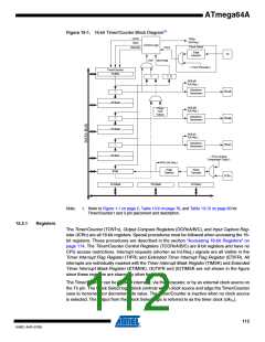
A simplified block diagram of the 16-bit Timer/Counter is shown in Figure 15-1. CPU accessible
I/O Registers, including I/O bits and I/O pins, are shown in bold.
111
8160C–AVR–07/09

 ATMEL [ ATMEL ]