ATmega64A
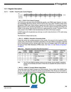
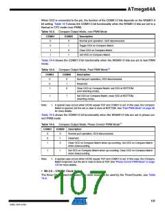
When OC0 is connected to the pin, the function of the COM01:0 bits depends on the WGM01:0
bit setting. Table 14-3 shows the COM01:0 bit functionality when the WGM01:0 bits are set to a
Normal or CTC mode (non-PWM).
Table 14-3. Compare Output Mode, non-PWM Mode
COM01
COM00
Description
0
0
1
1
0
1
0
1
Normal port operation, OC0 disconnected.
Toggle OC0 on Compare Match.
Clear OC0 on Compare Match.
Set OC0 on Compare Match.
Table 14-4 shows the COM01:0 bit functionality when the WGM01:0 bits are set to fast PWM
mode.
Table 14-4. Compare Output Mode, Fast PWM Mode(1)
COM01
COM00
Description
0
0
1
0
1
0
Normal port operation, OC0 disconnected.
Reserved
Clear OC0 on Compare Match, set OC0 at BOTTOM,
(non-inverting mode).
1
1
Set OC0 on Compare Match, clear OC0 at BOTTOM,
(inverting mode).
Note:
1. A special case occurs when OCR0 equals TOP and COM01 is set. In this case, the Compare
Match is ignored, but the set or clear is done at BOTTOM. See “Fast PWM Mode” on page 98
for more details.
Table 14-5 shows the COM01:0 bit functionality when the WGM01:0 bits are set to phase cor-
rect PWM mode.
Table 14-5. Compare Output Mode, Phase Correct PWM Mode(1)
COM01
COM00
Description
0
0
1
0
1
0
Normal port operation, OC0 disconnected.
Reserved.
Clear OC0 on Compare Match when up-counting. Set OC0 on Compare Match
when downcounting.
1
1
Set OC0 on Compare Match when up-counting. Clear OC0 on Compare Match
when downcounting.
Note:
1. A special case occurs when OCR0 equals TOP and COM01 is set. In this case, the Compare
Match is ignored, but the set or clear is done at TOP. See “Phase Correct PWM Mode” on page
100 for more details.
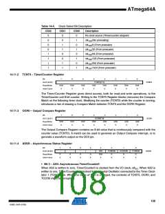
• Bit 2:0 – CS02:0: Clock Select
The three Clock Select bits select the clock source to be used by the Timer/Counter, see Table
14-6.
107
8160C–AVR–07/09

 ATMEL [ ATMEL ]