ATmega48PA/88PA/168PA/328P
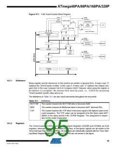
Figure 14-1. 8-bit Timer/Counter Block Diagram
Count
Clear
TOVn
(Int.Req.)
Control Logic
Clock Select
Direction
clkTn
Edge
Detector
Tn
TOP
BOTTOM
( From Prescaler )
Timer/Counter
TCNTn
=
=
0
OCnA
(Int.Req.)
Waveform
Generation
OCnA
=
OCRnA
Fixed
TOP
Value
OCnB
(Int.Req.)
Waveform
Generation
OCnB
=
OCRnB
TCCRnA
TCCRnB
14.2.1
Definitions
Many register and bit references in this section are written in general form. A lower case “n”
replaces the Timer/Counter number, in this case 0. A lower case “x” replaces the Output Com-
pare Unit, in this case Compare Unit A or Compare Unit B. However, when using the register or
bit defines in a program, the precise form must be used, i.e., TCNT0 for accessing
Timer/Counter0 counter value and so on.
The definitions in Table 14-1 are also used extensively throughout the document.
Table 14-1. Definitions
BOTTOM
MAX
The counter reaches the BOTTOM when it becomes 0x00.
The counter reaches its MAXimum when it becomes 0xFF (decimal 255).
TOP
The counter reaches the TOP when it becomes equal to the highest value in the
count sequence. The TOP value can be assigned to be the fixed value 0xFF
(MAX) or the value stored in the OCR0A Register. The assignment is depen-
dent on the mode of operation.
14.2.2
Registers
The Timer/Counter (TCNT0) and Output Compare Registers (OCR0A and OCR0B) are 8-bit
registers. Interrupt request (abbreviated to Int.Req. in the figure) signals are all visible in the
Timer Interrupt Flag Register (TIFR0). All interrupts are individually masked with the Timer Inter-
rupt Mask Register (TIMSK0). TIFR0 and TIMSK0 are not shown in the figure.
95
8161D–AVR–10/09

 ATMEL [ ATMEL ]