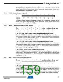
• Bit 1 – OCF2A: Output Compare Flag 2 A
The OCF2A bit is set (one) when a compare match occurs between the Timer/Counter2 and the
data in OCR2A – Output Compare Register2. OCF2A is cleared by hardware when executing
the corresponding interrupt handling vector. Alternatively, OCF2A is cleared by writing a logic
one to the flag. When the I-bit in SREG, OCIE2A (Timer/Counter2 Compare match Interrupt
Enable), and OCF2A are set (one), the Timer/Counter2 Compare match Interrupt is executed.
• Bit 0 – TOV2: Timer/Counter2 Overflow Flag
The TOV2 bit is set (one) when an overflow occurs in Timer/Counter2. TOV2 is cleared by hard-
ware when executing the corresponding interrupt handling vector. Alternatively, TOV2 is cleared
by writing a logic one to the flag. When the SREG I-bit, TOIE2A (Timer/Counter2 Overflow Inter-
rupt Enable), and TOV2 are set (one), the Timer/Counter2 Overflow interrupt is executed. In
PWM mode, this bit is set when Timer/Counter2 changes counting direction at 0x00.
17.11.8 ASSR – Asynchronous Status Register
Bit
(0xB6)
7
6
5
4
3
2
1
0
–
EXCLK
AS2
R/W
0
TCN2UB
OCR2AUB
OCR2BUB
TCR2AUB
TCR2BUB
ASSR
Read/Write
Initial Value
R
0
R/W
0
R
0
R
0
R
0
R
0
R
0
• Bit 7 – RES: Reserved bit
This bit is reserved and will always read as zero.
• Bit 6 – EXCLK: Enable External Clock Input
When EXCLK is written to one, and asynchronous clock is selected, the external clock input
buffer is enabled and an external clock can be input on Timer Oscillator 1 (TOSC1) pin instead
of a 32 kHz crystal. Writing to EXCLK should be done before asynchronous operation is
selected. Note that the crystal Oscillator will only run when this bit is zero.
• Bit 5 – AS2: Asynchronous Timer/Counter2
When AS2 is written to zero, Timer/Counter2 is clocked from the I/O clock, clkI/O. When AS2 is
written to one, Timer/Counter2 is clocked from a crystal Oscillator connected to the Timer Oscil-
lator 1 (TOSC1) pin. When the value of AS2 is changed, the contents of TCNT2, OCR2A,
OCR2B, TCCR2A and TCCR2B might be corrupted.
• Bit 4 – TCN2UB: Timer/Counter2 Update Busy
When Timer/Counter2 operates asynchronously and TCNT2 is written, this bit becomes set.
When TCNT2 has been updated from the temporary storage register, this bit is cleared by hard-
ware. A logical zero in this bit indicates that TCNT2 is ready to be updated with a new value.
• Bit 3 – OCR2AUB: Output Compare Register2 Update Busy
When Timer/Counter2 operates asynchronously and OCR2A is written, this bit becomes set.
When OCR2A has been updated from the temporary storage register, this bit is cleared by hard-
ware. A logical zero in this bit indicates that OCR2A is ready to be updated with a new value.
• Bit 2 – OCR2BUB: Output Compare Register2 Update Busy
When Timer/Counter2 operates asynchronously and OCR2B is written, this bit becomes set.
When OCR2B has been updated from the temporary storage register, this bit is cleared by hard-
ware. A logical zero in this bit indicates that OCR2B is ready to be updated with a new value.
160
ATmega48/88/168
2545M–AVR–09/07

 ATMEL [ ATMEL ]