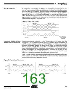
ATmega8(L)
Bit Rate Generator Unit
This unit controls the period of SCL when operating in a Master mode. The SCL period
is controlled by settings in the TWI Bit Rate Register (TWBR) and the Prescaler bits in
the TWI Status Register (TWSR). Slave operation does not depend on Bit Rate or Pres-
caler settings, but the CPU clock frequency in the Slave must be at least 16 times higher
than the SCL frequency. Note that slaves may prolong the SCL low period, thereby
reducing the average TWI bus clock period. The SCL frequency is generated according
to the following equation:
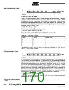
CPU Clock frequency
SCL frequency = -----------------------------------------------------------
TWPS
16 + 2(TWBR) 4
•
•
TWBR = Value of the TWI Bit Rate Register.
TWPS = Value of the prescaler bits in the TWI Status Register.
Note:
TWBR should be 10 or higher if the TWI operates in Master mode. If TWBR is lower than
10, the Master may produce an incorrect output on SDA and SCL for the reminder of the
byte. The problem occurs when operating the TWI in Master mode, sending Start + SLA
+ R/W to a Slave (a Slave does not need to be connected to the bus for the condition to
happen).
Bus Interface Unit
This unit contains the Data and Address Shift Register (TWDR), a START/STOP Con-
troller and Arbitration detection hardware. The TWDR contains the address or data
bytes to be transmitted, or the address or data bytes received. In addition to the 8-bit
TWDR, the Bus Interface Unit also contains a register containing the (N)ACK bit to be
transmitted or received. This (N)ACK Register is not directly accessible by the applica-
tion software. However, when receiving, it can be set or cleared by manipulating the
TWI Control Register (TWCR). When in Transmitter mode, the value of the received
(N)ACK bit can be determined by the value in the TWSR.
The START/STOP Controller is responsible for generation and detection of START,
REPEATED START, and STOP conditions. The START/STOP controller is able to
detect START and STOP conditions even when the AVR MCU is in one of the sleep
modes, enabling the MCU to wake up if addressed by a Master.
If the TWI has initiated a transmission as Master, the Arbitration Detection hardware
continuously monitors the transmission trying to determine if arbitration is in process. If
the TWI has lost an arbitration, the Control Unit is informed. Correct action can then be
taken and appropriate status codes generated.
Address Match Unit
The Address Match unit checks if received address bytes match the seven-bit address
in the TWI Address Register (TWAR). If the TWI General Call Recognition Enable
(TWGCE) bit in the TWAR is written to one, all incoming address bits will also be com-
pared against the General Call address. Upon an address match, the Control Unit is
informed, allowing correct action to be taken. The TWI may or may not acknowledge its
address, depending on settings in the TWCR. The Address Match unit is able to com-
pare addresses even when the AVR MCU is in sleep mode, enabling the MCU to wake
up if addressed by a Master. If another interrupt (e.g., INT0) occurs during TWI Power-
down address match and wakes up the CPU, the TWI aborts operation and return to it’s
idle state. If this cause any problems, ensure that TWI Address Match is the only
enabled interrupt when entering Power-down.
Control Unit
The Control unit monitors the TWI bus and generates responses corresponding to set-
tings in the TWI Control Register (TWCR). When an event requiring the attention of the
application occurs on the TWI bus, the TWI Interrupt Flag (TWINT) is asserted. In the
next clock cycle, the TWI Status Register (TWSR) is updated with a status code identify-
ing the event. The TWSR only contains relevant status information when the TWI
167
2486M–AVR–12/03

 ATMEL [ ATMEL ]