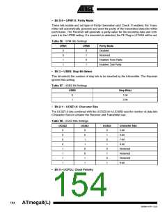
• Bit 5:4 – UPM1:0: Parity Mode
These bits enable and set type of Parity Generation and Check. If enabled, the Trans-
mitter will automatically generate and send the parity of the transmitted data bits within
each frame. The Receiver will generate a parity value for the incoming data and com-
pare it to the UPM0 setting. If a mismatch is detected, the PE Flag in UCSRA will be set.
Table 56. UPM Bits Settings
UPM1
UPM0
Parity Mode
0
0
1
1
0
1
0
1
Disabled
Reserved
Enabled, Even Parity
Enabled, Odd Parity
• Bit 3 – USBS: Stop Bit Select
This bit selects the number of stop bits to be inserted by the trAnsmitter. The Receiver
ignores this setting.
Table 57. USBS Bit Settings
USBS
Stop Bit(s)
1-bit
0
1
2-bit
• Bit 2:1 – UCSZ1:0: Character Size
The UCSZ1:0 bits combined with the UCSZ2 bit in UCSRB sets the number of data bits
(Character Size) in a frame the Receiver and Transmitter use.
Table 58. UCSZ Bits Settings
UCSZ2
UCSZ1
UCSZ0
Character Size
5-bit
0
0
0
0
1
1
1
1
0
0
1
1
0
0
1
1
0
1
0
1
0
1
0
1
6-bit
7-bit
8-bit
Reserved
Reserved
Reserved
9-bit
• Bit 0 – UCPOL: Clock Polarity
154
ATmega8(L)
2486M–AVR–12/03

 ATMEL [ ATMEL ]