ATmega8(L)
Programming the
Fuse High Bits
The algorithm for programming the Fuse high bits is as follows (refer to “Programming the Flash”
on page 222 for details on Command and Data loading):
1. A: Load Command “0100 0000”
2. C: Load Data Low byte. Bit n = “0” programs and bit n = “1” erases the Fuse bit
3. Set BS1 to “1” and BS2 to “0”. This selects high data byte
4. Give WR a negative pulse and wait for RDY/BSY to go high
5. Set BS1 to “0”. This selects low data byte
Programming the Lock The algorithm for programming the Lock Bits is as follows (refer to “Programming the Flash” on
Bits
page 222 for details on Command and Data loading):
1. A: Load Command “0010 0000”
2. C: Load Data Low byte. Bit n = “0” programs the Lock bit
3. Give WR a negative pulse and wait for RDY/BSY to go high
The Lock Bits can only be cleared by executing Chip Erase.
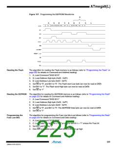
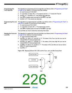
Reading the Fuse and The algorithm for reading the Fuse and Lock Bits is as follows (refer to “Programming the Flash”
Lock Bits
on page 222 for details on Command loading):
1. A: Load Command “0000 0100”
2. Set OE to “0”, BS2 to “0”, and BS1 to “0”. The status of the Fuse Low bits can now be
read at DATA (“0” means programmed)
3. Set OE to “0”, BS2 to “1”, and BS1 to “1”. The status of the Fuse High bits can now be
read at DATA (“0” means programmed)
4. Set OE to “0”, BS2 to “0”, and BS1 to “1”. The status of the Lock Bits can now be read at
DATA (“0” means programmed)
5. Set OE to “1”
Figure 108. Mapping Between BS1, BS2 and the Fuse- and Lock Bits During Read
Fuse low byte
Lock bits
0
DATA
0
1
Fuse high byte
1
BS1
BS2
226
2486AA–AVR–02/2013

 ATMEL [ ATMEL ]