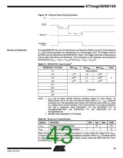
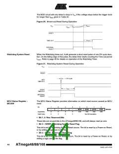
The BOD circuit will only detect a drop in VCC if the voltage stays below the trigger level
for longer than tBOD given in Table 20.
Figure 20. Brown-out Reset During Operation
VBOT+
VCC
VBOT-
RESET
t
TOUT
TIME-OUT
INTERNAL
RESET
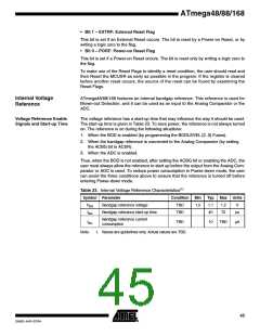
Watchdog System Reset
When the Watchdog times out, it will generate a short reset pulse of one CK cycle dura-
tion. On the falling edge of this pulse, the delay timer starts counting the Time-out period
tTOUT. Refer to page 46 for details on operation of the Watchdog Timer.
Figure 21. Watchdog System Reset During Operation
CC
CK
MCU Status Register –
MCUSR
The MCU Status Register provides information on which reset source caused an MCU
reset.
Bit
7
–
6
–
5
–
4
–
3
2
1
0
WDRF
R/W
BORF
R/W
EXTRF
R/W
PORF
R/W
MCUSR
Read/Write
Initial Value
R
0
R
0
R
0
R
0
See Bit Description
• Bit 7..4: Res: Reserved Bits
These bits are unused bits in the ATmega48/88/168, and will always read as zero.
• Bit 3 – WDRF: Watchdog System Reset Flag
This bit is set if a Watchdog System Reset occurs. The bit is reset by a Power-on Reset,
or by writing a logic zero to the flag.
• Bit 2 – BORF: Brown-out Reset Flag
This bit is set if a Brown-out Reset occurs. The bit is reset by a Power-on Reset, or by
writing a logic zero to the flag.
44
ATmega48/88/168
2545D–AVR–07/04

 ATMEL [ ATMEL ]