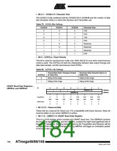
• Bit 2:1 – UCSZn1:0: Character Size
The UCSZn1:0 bits combined with the UCSZn2 bit in UCSRnB sets the number of data
bits (Character SiZe) in a frame the Receiver and Transmitter use.
Table 79. UCSZn Bits Settings
UCSZn2
UCSZn1
UCSZn0
Character Size
5-bit
0
0
0
0
1
1
1
1
0
0
1
1
0
0
1
1
0
1
0
1
0
1
0
1
6-bit
7-bit
8-bit
Reserved
Reserved
Reserved
9-bit
• Bit 0 – UCPOLn: Clock Polarity
This bit is used for synchronous mode only. Write this bit to zero when asynchronous
mode is used. The UCPOLn bit sets the relationship between data output change and
data input sample, and the synchronous clock (XCKn).
Table 80. UCPOLn Bit Settings
Transmitted Data Changed (Output
of TxDn Pin)
Received Data Sampled (Input on
RxDn Pin)
UCPOLn
0
1
Rising XCKn Edge
Falling XCKn Edge
Falling XCKn Edge
Rising XCKn Edge
USART Baud Rate Registers –
UBRRnL and UBRRnH
Bit
15
14
13
12
11
10
9
8
–
–
–
–
UBRRn[11:8]
UBRRnH
UBRRnL
UBRRn[7:0]
7
R
6
R
5
R
4
R
3
R/W
R/W
0
2
R/W
R/W
0
1
R/W
R/W
0
0
R/W
R/W
0
Read/Write
Initial Value
R/W
0
R/W
0
R/W
0
R/W
0
0
0
0
0
0
0
0
0
• Bit 15:12 – Reserved Bits
These bits are reserved for future use. For compatibility with future devices, these bit
must be written to zero when UBRRnH is written.
• Bit 11:0 – UBRR11:0: USART Baud Rate Register
This is a 12-bit register which contains the USART baud rate. The UBRRnH contains
the four most significant bits, and the UBRRnL contains the eight least significant bits of
the USART baud rate. Ongoing transmissions by the Transmitter and Receiver will be
corrupted if the baud rate is changed. Writing UBRRnL will trigger an immediate update
of the baud rate prescaler.
184
ATmega48/88/168
2545D–AVR–07/04

 ATMEL [ ATMEL ]