USART0
The Universal Synchronous and Asynchronous serial Receiver and Transmitter
(USART) is a highly flexible serial communication device. The main features are:
• Full Duplex Operation (Independent Serial Receive and Transmit Registers)
• Asynchronous or Synchronous Operation
• Master or Slave Clocked Synchronous Operation
• High Resolution Baud Rate Generator
• Supports Serial Frames with 5, 6, 7, 8, or 9 Data Bits and 1 or 2 Stop Bits
• Odd or Even Parity Generation and Parity Check Supported by Hardware
• Data OverRun Detection
• Framing Error Detection
• Noise Filtering Includes False Start Bit Detection and Digital Low Pass Filter
• Three Separate Interrupts on TX Complete, TX Data Register Empty and RX Complete
• Multi-processor Communication Mode
• Double Speed Asynchronous Communication Mode
The USART can also be used in Master SPI mode, see “USART in SPI Mode” on page
189. The Power Reduction USART bit, PRUSART0, in “Power Reduction Register -
PRR” on page 37 must be disabled by writing a logical zero to it.
Overview
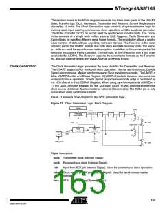
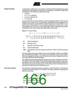
A simplified block diagram of the USART Transmitter is shown in Figure 70. CPU acces-
sible I/O Registers and I/O pins are shown in bold.
Figure 70. USART Block Diagram(1)
Clock Generator
UBRRn[H:L]
OSC
BAUD RATE GENERATOR
SYNC LOGIC
PIN
XCKn
CONTROL
Transmitter
TX
CONTROL
UDRn(Transmit)
PARITY
GENERATOR
PIN
CONTROL
TRANSMIT SHIFT REGISTER
TxDn
Receiver
CLOCK
RECOVERY
RX
CONTROL
DATA
RECOVERY
PIN
CONTROL
RECEIVE SHIFT REGISTER
RxDn
PARITY
CHECKER
UDRn(Receive)
UCSRnA
UCSRnB
UCSRnC
Note:
1. Refer to Figure 1 on page 2 and Table 39 on page 75 for USART0 pin placement.
162
ATmega48/88/168
2545D–AVR–07/04

 ATMEL [ ATMEL ]