• Bit 2 – PE: Parity Error
This bit is set if the next character in the receive buffer had a Parity Error when received
and the parity checking was enabled at that point (UPM1 = 1). This bit is valid until the
receive buffer (UDR) is read. Always set this bit to zero when writing to UCSRA.
• Bit 1 – U2X: Double the USART Transmission Speed
This bit only has effect for the asynchronous operation. Write this bit to zero when using
synchronous operation.
Writing this bit to one will reduce the divisor of the baud rate divider from 16 to 8 effec-
tively doubling the transfer rate for asynchronous communication.
• Bit 0 – MPCM: Multi-processor Communication Mode
This bit enables the Multi-processor Communication mode. When the MPCM bit is writ-
ten to one, all the incoming frames received by the USART receiver that do not contain
address information will be ignored. The transmitter is unaffected by the MPCM setting.
For more detailed information see “Multi-processor Communication Mode” on page 154.
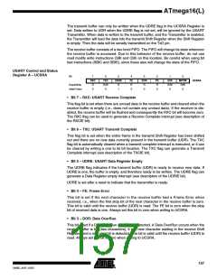
USART Control and Status
Register B – UCSRB
Bit
7
RXCIE
R/W
0
6
TXCIE
R/W
0
5
UDRIE
R/W
0
4
RXEN
R/W
0
3
TXEN
R/W
0
2
UCSZ2
R/W
0
1
RXB8
R
0
TXB8
R/W
0
UCSRB
Read/Write
Initial Value
0
• Bit 7 – RXCIE: RX Complete Interrupt Enable
Writing this bit to one enables interrupt on the RXC flag. A USART Receive Complete
Interrupt will be generated only if the RXCIE bit is written to one, the Global Interrupt
Flag in SREG is written to one and the RXC bit in UCSRA is set.
• Bit 6 – TXCIE: TX Complete Interrupt Enable
Writing this bit to one enables interrupt on the TXC flag. A USART Transmit Complete
Interrupt will be generated only if the TXCIE bit is written to one, the Global Interrupt
Flag in SREG is written to one and the TXC bit in UCSRA is set.
• Bit 5 – UDRIE: USART Data Register Empty Interrupt Enable
Writing this bit to one enables interrupt on the UDRE flag. A Data Register Empty Inter-
rupt will be generated only if the UDRIE bit is written to one, the Global Interrupt Flag in
SREG is written to one and the UDRE bit in UCSRA is set.
• Bit 4 – RXEN: Receiver Enable
Writing this bit to one enables the USART Receiver. The Receiver will override normal
port operation for the RxD pin when enabled. Disabling the Receiver will flush the
receive buffer invalidating the FE, DOR, and PE flags.
• Bit 3 – TXEN: Transmitter Enable
Writing this bit to one enables the USART Transmitter. The Transmitter will override nor-
mal port operation for the TxD pin when enabled. The disabling of the Transmitter
(writing TXEN to zero) will not become effective until ongoing and pending transmis-
sions are completed, i.e., when the transmit Shift Register and transmit Buffer Register
158
ATmega16(L)
2466E–AVR–10/02

 ATMEL [ ATMEL ]