ATmega169P
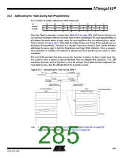
The page address must be written to PCPAGE. Other bits in the Z-pointer must be written to
zero during this operation.
• Page Write to the RWW section: The NRWW section can be read during the Page Write.
• Page Write to the NRWW section: The CPU is halted during the operation.
25.7.4
25.7.5
25.7.6
Using the SPM Interrupt
If the SPM interrupt is enabled, the SPM interrupt will generate a constant interrupt when the
SPMEN bit in SPMCSR is cleared. This means that the interrupt can be used instead of polling
the SPMCSR Register in software. When using the SPM interrupt, the Interrupt Vectors should
be moved to the BLS section to avoid that an interrupt is accessing the RWW section when it is
blocked for reading. How to move the interrupts is described in ”Interrupts” on page 56.
Consideration While Updating BLS
Special care must be taken if the user allows the Boot Loader section to be updated by leaving
Boot Lock bit11 unprogrammed. An accidental write to the Boot Loader itself can corrupt the
entire Boot Loader, and further software updates might be impossible. If it is not necessary to
change the Boot Loader software itself, it is recommended to program the Boot Lock bit11 to
protect the Boot Loader software from any internal software changes.
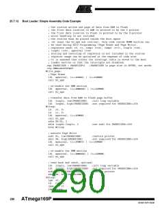
Prevent Reading the RWW Section During Self-Programming
During Self-Programming (either Page Erase or Page Write), the RWW section is always
blocked for reading. The user software itself must prevent that this section is addressed during
the self programming operation. The RWWSB in the SPMCSR will be set as long as the RWW
section is busy. During Self-Programming the Interrupt Vector table should be moved to the BLS
as described in ”Interrupts” on page 56, or the interrupts must be disabled. Before addressing
the RWW section after the programming is completed, the user software must clear the
RWWSB by writing the RWWSRE. See ”Boot Loader: Simple Assembly Code Example” on
page 290 for an example.
25.7.7
Setting the Boot Loader Lock Bits by SPM
To set the Boot Loader Lock bits and general Lock bits, write the desired data to R0, write
“X0001001” to SPMCSR and execute SPM within four clock cycles after writing SPMCSR.
Bit
7
6
5
4
3
2
1
0
R0
1
1
BLB12
BLB11
BLB02
BLB01
LB2
LB1
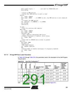
See Table 25-2 and Table 25-3 for how the different settings of the Boot Loader bits affect the
Flash access.
If bits 5..2 in R0 are cleared (zero), the corresponding Boot Lock bit will be programmed if an
SPM instruction is executed within four cycles after BLBSET and SPMEN are set in SPMCSR.
The Z-pointer is don’t care during this operation, but for future compatibility it is recommended to
load the Z-pointer with 0x0001 (same as used for reading the Lock bits). For future compatibility
it is also recommended to set bits 7 and 6 in R0 to “1” when writing the Lock bits. When pro-
gramming the Lock bits the entire Flash can be read during the operation.
287
8018A–AVR–03/06

 ATMEL [ ATMEL ]