• Bit 6– AC2IE: Analog Comparator 2 Interrupt Enable bit
Set this bit to enable the analog comparator 2 interrupt.
Clear this bit to disable the analog comparator 2 interrupt.
• Bit 5, 4– AC2IS1, AC2IS0: Analog Comparator 2 Interrupt Select bit
These 2 bits determine the sensitivity of the interrupt trigger.
The different setting are shown in Table 20-1.
Table 20-5. Interrupt sensitivity selection
AC2IS1
AC2IS0
Description
0
0
1
1
0
1
0
1
Comparator Interrupt on output toggle
Reserved
Comparator interrupt on output falling edge
Comparator interrupt on output rising edge
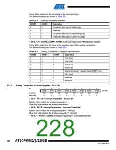
• Bit 2, 1, 0– AC2M2, AC2M1, AC2M0: Analog Comparator 2 Multiplexer register
These 3 bits determine the input of the negative input of the analog comparator.
The different setting are shown in Table 20-6.
Table 20-6. Analog Comparator 2 negative input selection
AC2M2
AC2M1
AC2M0
Description
0
0
0
0
1
1
1
1
0
0
1
1
0
0
1
1
0
1
0
1
0
1
0
1
“Vref”/6.40
“Vref”/3.20
“Vref”/2.13
“Vref”/1.60
Analog Comparator Negative Input (ACMPM pin)
DAC result
Reserved
Reserved
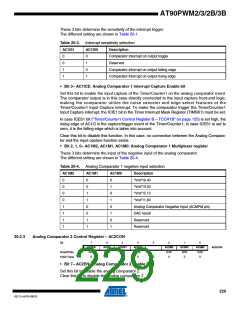
20.2.4
Analog Comparator Status Register – ACSR
Bit
7
ACCKDIV
R/W
6
AC2IF
R/W
0
5
AC1IF
R/W
0
4
AC0IF
R/W
0
3
-
2
AC2O
R
1
AC1O
R
0
AC0O
R
ACSR
Read/Write
Initial Value
-
0
0
0
0
0
• Bit 7– ACCKDIV: Analog Comparator Clock Divider
The analog comparators can work with a clock up to 8MHz@3V and 16MHz@5V.
Set this bit in case the clock frequency of the microcontroller is higher than 8 MHz to insert a
divider by 2 between the clock of the microcontroller and the clock of the analog comparators.
Clear this bit to have the same clock frequency for the microcontroller and the analog
comparators.
• Bit 6– AC2IF: Analog Comparator 2 Interrupt Flag Bit
This bit is set by hardware when comparator 2 output event triggers off the interrupt mode
defined by AC2IS1 and AC2IS0 bits in AC2CON register.
This bit is cleared by hardware when the corresponding interrupt vector is executed in case the
230
AT90PWM2/3/2B/3B
4317J–AVR–08/10

 ATMEL [ ATMEL ]