AT90PWM2/3/2B/3B
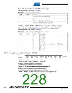
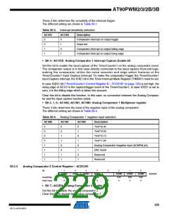
These 2 bits determine the sensitivity of the interrupt trigger.
The different setting are shown in Table 20-1.
Table 20-3. Interrupt sensitivity selection
AC1IS1
AC1IS0
Description
0
0
1
1
0
1
0
1
Comparator Interrupt on output toggle
Reserved
Comparator interrupt on output falling edge
Comparator interrupt on output rising edge
• Bit 3– AC1ICE: Analog Comparator 1 Interrupt Capture Enable bit
Set this bit to enable the input capture of the Timer/Counter1 on the analog comparator event.
The comparator output is in this case directly connected to the input capture front-end logic,
making the comparator utilize the noise canceler and edge select features of the
Timer/Counter1 Input Capture interrupt. To make the comparator trigger the Timer/Counter1
Input Capture interrupt, the ICIE1 bit in the Timer Interrupt Mask Register (TIMSK1) must be set.
In case ICES1 bit (“Timer/Counter1 Control Register B – TCCR1B” on page 125) is set high, the
rising edge of AC1O is the capture/trigger event of the Timer/Counter1, in case ICES1 is set to
zero, it is the falling edge which is taken into account.
Clear this bit to disable this function. In this case, no connection between the Analog Compara-
tor and the input capture function exists.
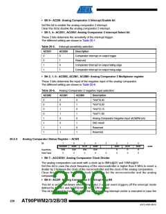
• Bit 2, 1, 0– AC1M2, AC1M1, AC1M0: Analog Comparator 1 Multiplexer register
These 3 bits determine the input of the negative input of the analog comparator.
The different setting are shown in Table 20-4.
Table 20-4. Analog Comparator 1 negative input selection
AC1M2
AC1M1
AC1M0
Description
0
0
0
0
1
1
1
1
0
0
1
1
0
0
1
1
0
1
0
1
0
1
0
1
“Vref”/6.40
“Vref”/3.20
“Vref”/2.13
“Vref”/1.60
Analog Comparator Negative Input (ACMPM pin)
DAC result
Reserved
Reserved
20.2.3
Analog Comparator 2 Control Register – AC2CON
Bit
7
AC2EN
R/W
0
6
AC2IE
R/W
0
5
AC2IS1
R/W
0
4
AC2IS0
R/W
0
3
2
AC2M2
R/W
0
1
AC2M1
R/W
0
0
AC2M0
R/W
0
AC2CON
Read/Write
Initial Value
-
0
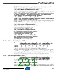
• Bit 7– AC2EN: Analog Comparator 2 Enable Bit
Set this bit to enable the analog comparator 2.
Clear this bit to disable the analog comparator 2.
229
4317J–AVR–08/10

 ATMEL [ ATMEL ]