When set the EUSART operates in manchester encoder/decoder mode (Manchester encoded
frames). When cleared the EUSART detected and transmit level encoded frames.
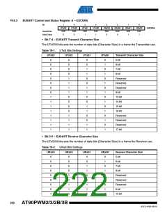
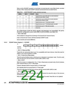
Table 19-4. USART/EUSART modes selection summary
UMSEL
EMCH
EUSART
Mode
Asynchronous up to 9 bits level encoded (standard
asynchronous USART mode)
0
X
0
Synchronous up to 9 bits level encoded (standard
synchronous USART mode)
1
X
0
0
0
1
1
0
1
0
1
1
1
1
1
Asynchronous up to 17 bits level encoded
Asynchronous up to 17 bits Manchester encoded
Synchronous up to 17 bits level encoded
Reserved
As in Manchester mode the parity checker and generator are unavailable, the parity
should be configured to none ( write UPM1:0 to 00 in UCSRC), see Table 18-5.
• Bit 0 –Bit Order
This bit allows to change the bit ordering in the transmit and received frames.
Clear to transmit and receive LSB first (standard USART mode)
Set to transmit and receive MSB first.
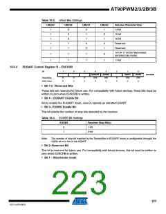
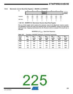
19.6.5
EUSART Status Register C – EUCSRC
Bit
7
6
-
5
-
4
-
3
FEM
R
2
F1617
R
1
STP1
R
0
STP0
R
-
EUCSRC
Read/Write
Initial Value
R
0
R
0
R
0
R
0
0
0
0
0
• Bit 7:4 –Reserved Bits
These bits are reserved for future use. For compatibilty with future devices, these bits must be
written to zero when EUSCRC is written.
• Bit 3 –Frame Error Manchester
This bit is set by hardware when a framing error is detected in manchester mode. This bit is valid
when the RxC bit is set and until the receive buffer (UDR) is read.
• Bit 2 –F1617
When the receiver is configured for 16 or 17 bits in Manchester encoded mode, this bit indicates
if the received frame is 16 or 17 bits lenght.
Cleared: indicates that the received frame is 16 bits lenght.
Set: Indicates that the received frame is 17 bits lenght.
This bit is valid when the RxC bit is set and until the receive buffer (UDR) is read.
• Bit 1:0 –Stop bits values
When Manchester mode is activated, these bits contains the stop bits value of the previous
received frame.
When the data bits in the serial frame are standard level encoded, these bits are not updated.
224
AT90PWM2/3/2B/3B
4317J–AVR–08/10

 ATMEL [ ATMEL ]