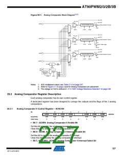
AT90PWM2/3/2B/3B
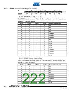
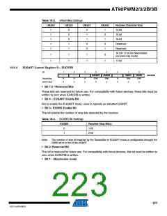
Table 19-2. URxS Bits Settings
URxS3
URxS2
URxS1
URxS0
Receive Character Size
1
1
1
1
1
0
0
0
1
1
0
1
1
0
0
1
0
1
0
1
14-bit
15-bit
16-bit
Reserved
Reserved
16 OR 17 bit (for Manchester
encoded only mode)
1
1
1
1
1
1
0
1
17-bit
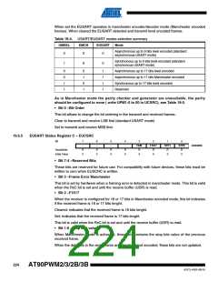
19.6.4
EUSART Control Register B – EUCSRB
Bit
7
-
6
-
5
-
4
EUSART
R/W
3
EUSBS
R/W
0
2
-
1
EMCH
R/W
0
0
BODR
R/W
0
EUCSRB
Read/Write
Initial Value
R
0
R
0
R
0
R
0
0
• Bit 7:5 –Reserved Bits
These bits are reserved for future use. For compatibilty with future devices, these bits must be
written to zero when EUSCRB is written.
• Bit 4 – EUSART Enable Bit
Set to enable the EUSART mode, clear to operate as standard USART.
• Bit 3– EUSBS Enable Bit
This bit selects the number of stop bits detected by the receiver.
Table 19-3. EUSBS Bit Settings
EUSBS
Receiver Stop Bit(s)
0
1
1-bit
2-bit
Note:
The number of stop bit inserted by the Transmitter in EUSART mode is configurable throught the
USBS bit of in the of the USART.
• Bit 2–Reserved Bit
This bit is reserved for future use. For compatibilty with future devices, this bit must be written to
zero when EUSCRB is written.
• Bit 1 – Manchester mode
223
4317J–AVR–08/10

 ATMEL [ ATMEL ]