19.4.4
19.4.5
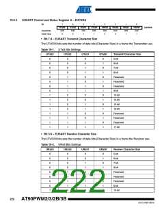
Sending 17 Data Bit Frames
In this configuration the seventeenth bit shoud be loaded in the RXB8 bit register, the rest of the
most significant bits (9, 10, 11, 12, 13, 14, 15 and 16) should be loaded in the EUDR register,
before the low byte of the character is written to UDR.
Transmitter Flags and Interrupts
The behavior of the EUSART is the same as in USART mode (See “Receive Complete Flag and
Interrupt”).
The interrupts generation and handling for transmission in EUSART mode are the same as in
USART mode.
19.4.6
19.4.7
Disabling the Transmitter
The disabling of the Transmitter (setting the TXEN to zero) will not become effective until ongo-
ing and pending transmissions are completed, i.e., when the Transmit Shift Register and
Transmit Buffer Register do not contain data to be transmitted.
Data Reception – EUSART Receiver
19.5 Data Reception – EUSART Receiver
The EUSART Receiver is enabled by writing the Receive Enable (RXEN) bit in the UCSRB Reg-
ister to one (same as USART). When the Receiver is enabled, the normal pin operation of the
RxD pin is overridden by the EUSART and given the function as the Receiver’s serial input. The
baud rate, mode of operation and frame format must be set up once before any serial reception
can be done. If synchronous operation is used, the clock on the XCK pin will be used as transfer
clock.
19.5.1
19.5.2
Receiving Frames with 5 to 8 Data Bits
In this mode the behavior is the same as the standard USART (See “Receiving Frames with 5 to
8 Data Bits” in USART section).
Receiving Frames with 9, 13, 14, 15 or 16 Data Bits
In these configurations the most significant bits (9, 13, 14, 15 or 16) should be read in the EUDR
register before reading the of the character in the UDR register.
Read status from EUCSRC, then data from UDR.
218
AT90PWM2/3/2B/3B
4317J–AVR–08/10

 ATMEL [ ATMEL ]