AT90PWM2/3/2B/3B
19.4 Configuring the EUSART
19.4.1
Data Transmission – EUSART Transmitter
The EUSART Transmitter is enabled in the same way as standard USART, by setting the Trans-
mit Enable (TXEN) bit in the UCSRB Register. When the Transmitter is enabled, the normal port
operation of the TxDn pin is overridden by the EUSART and given the function as the Transmit-
ter’s serial output. The baud rate, mode of operation and frame format must be set up once
before doing any transmissions. If synchronous operation is used, the clock on the XCK pin will
be overridden and used as transmission clock.
19.4.2
19.4.3
Sending Frames with 5 to 8 Data Bit
In this mode the behavior is the same as the standard USART (See “Sending Frames with 5 to 8
Data Bit” in USART section).
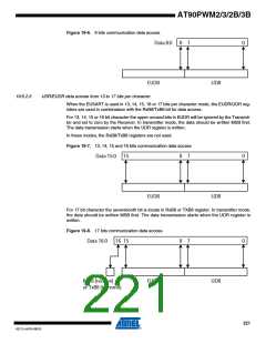
Sending Frames with 9, 13, 14, 15 or 16 Data Bit
In these configurations the most significant bits (9, 13, 14, 15 or 16) should be loaded in the
EUDR register before the low byte of the character is written to UDR. The write operation in the
UDR register allows to start the transmission.
TABLE 2.
Assembly Code Example(1)
EUSART_Transmit:
; Wait for empty transmit buffer
sbis UCSRA,UDRE
rjmp EUSART_Transmit
; Put LSB data (r16) and MSN data (r15) into buffer, sends the data
sts EUDR,r15
sts UDR,r16
ret
C Code Example(1)
void EUSART_Transmit( unsigned int data )
{
/* Wait for empty transmit buffer */
while ( !( UCSRA & (1<<UDRE))) )
/* Put data into buffer, sends the data */
EUDR = data>>8;
UDR = data;
}
Note:
The example code assumes that the part specific header file is included.
For I/O Registers located in extended I/O map, “IN”, “OUT”, “SBIS”, “SBIC”, “CBI”, and “SBI”
instructions must be replaced with instructions that allow access to extended I/O. Typically “LDS”
and “STS” combined with “SBRS”, “SBRC”, “SBR”, and “CBR”.
217
4317J–AVR–08/10

 ATMEL [ ATMEL ]