AT42QT1011
3.4
Detect Integrator
It is desirable to suppress detections generated by electrical noise or from quick brushes with an
object. To accomplish this, the QT1011 incorporates a detect integration (DI) counter that
increments with each detection until a limit is reached, after which the output is activated. If no
detection is sensed prior to the final count, the counter is reset immediately to zero. In the
QT1011, the required count is four. In LP mode the device will switch to Fast mode temporarily
in order to resolve the detection more quickly; after a touch is either confirmed or denied the
device will revert back to normal LP mode operation automatically.
The DI can also be viewed as a “consensus filter” that requires four successive detections to
create an output.
3.5
3.6
Forced Sensor Recalibration
The QT1011 has no recalibration pin; a forced recalibration is accomplished when the device is
powered up or after the recalibration timeout. However, supply drain is low so it is a simple
matter to treat the entire IC as a controllable load; driving the QT1011's Vdd pin directly from
another logic gate or a microcontroller port will serve as both power and “forced recalibration”.
The source resistance of most CMOS gates and microcontrollers is low enough to provide direct
power without problem.
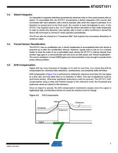
Drift Compensation
Signal drift can occur because of changes in Cx and Cs over time. It is crucial that drift be
compensated for, otherwise false detections, nondetections, and sensitivity shifts will follow.
Drift compensation (Figure 3-5) is performed by making the reference level track the raw signal
at a slow rate, but only while there is no detection in effect. The rate of adjustment must be
performed slowly, otherwise legitimate detections could be ignored. The QT1011 drift
compensates using a slew-rate limited change to the reference level; the threshold and
hysteresis values are slaved to this reference.
Once an object is sensed, the drift compensation mechanism ceases since the signal is
legitimately high, and therefore should not cause the reference level to change.
Figure 3-5. Drift Compensation
Signal
Hysteresis
Threshold
Reference
Output
7
9542G–AT42–03/10

 ATMEL [ ATMEL ]