AT42QT1011
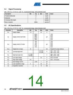
5.6
Mechanical Dimensions
D
A
5
6
4
A2
A1
E
E1
A
Pin #1 ID
C
0.10
SEATING PLANE
A
1
3
2
C
Side View
b
e
Top View
A2
A
C
0.10
SEATING PLANE
c
0.25
C
A1
SEATING PLANE
View A-A
C
SEE VIEW B
O
L
View B
COMMON DIMENSIONS
(Unit of Measure = mm)
MIN
–
MAX
1.45
0.15
1.30
3.00
3.00
1.75
0.55
NOM
–
NOTE
SYMBOL
A
A1
A2
D
E
0
–
0.90
2.80
2.60
1.50
0.30
–
2.90
2.80
1.60
0.45
0.95 BSC
–
2
E1
L
Notes: 1. This package is compliant with JEDEC specification MO-178 Variation AB
2. Dimension D does not include mold Flash, protrusions or gate burrs.
Mold Flash, protrustion or gate burrs shall not exceed 0.25 mm per end.
3. Dimension b does not include dambar protrusion. Allowable dambar
protrusion shall not cause the lead width to exceed the maximum
b dimension by more than 0.08 mm
e
b
0.30
0.09
0°
0.50
0.20
8°
3
c
–
θ
–
4. Die is facing down after trim/form.
6/30/08
GPC
TAQ
DRAWING NO.
TITLE
REV.
6ST1, 6-lead, 2.90 x 1.60 mm Plastic Small Outline
Package Drawing Contact:
packagedrawings@atmel.com
6ST1
A
Package (SOT23)
15
9542G–AT42–03/10

 ATMEL [ ATMEL ]