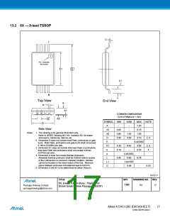
13.2 8X — 8-lead TSSOP
C
1
Pin 1 indicator
this corner
E1
E
L1
N
L
Top View
End View
A
b
A1
COMMON DIMENSIONS
(Unit of Measure = mm)
e
A2
MIN
-
MAX
1.20
NOM
-
NOTE
2, 5
SYMBOL
D
A
Side View
A1
A2
D
0.05
0.80
2.90
-
0.15
Notes: 1. This drawing is for general information only.
Refer to JEDEC Drawing MO-153, Variation AA, for proper
dimensions, tolerances, datums, etc.
1.00
3.00
1.05
3.10
2. Dimension D does not include mold Flash, protrusions or gate
burrs. Mold Flash, protrusions and gate burrs shall not exceed
0.15mm (0.006in) per side.
3. Dimension E1 does not include inter-lead Flash or protrusions.
Inter-lead Flash and protrusions shall not exceed 0.25mm
(0.010in) per side.
4. Dimension b does not include Dambar protrusion.
Allowable Dambar protrusion shall be 0.08mm total in excess
of the b dimension at maximum material condition. Dambar
cannot be located on the lower radius of the foot. Minimum
space between protrusion and adjacent lead is 0.07mm.
5. Dimension D and E1 to be determined at Datum Plane H.
E
6.40 BSC
4.50
E1
b
4.30
0.19
4.40
–
3, 5
4
0.30
e
0.65 BSC
0.60
L
0.45
0.75
-
L1
C
1.00 REF
0.09
0.20
6/22/11
TITLE
GPC
TNR
DRAWING NO.
REV.
8X, 8-lead 4.4mm Body, Plastic Thin
Shrink Small Outline Package (TSSOP)
8X
D
Package Drawing Contact:
packagedrawings@atmel.com
Atmel AT24C128C [DATASHEET]
17
8734B–SEEPR–9/2012

 ATMEL [ ATMEL ]