AT90USB82/162
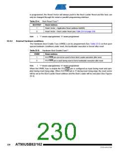
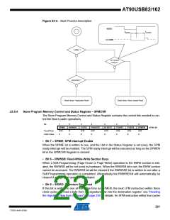
Figure 23-3. Boot Process Description
RESET
tSHRH
tHHRH
PD7/HWB
HWBE ?
Ext. Hardware
Conditions ?
BOOTRST ?
Reset Vector = Application Reset
Reset Vector =Boot Lhoader Reset
23.5.4
Store Program Memory Control and Status Register – SPMCSR
The Store Program Memory Control and Status Register contains the control bits needed to con-
trol the Boot Loader operations.
Bit
7
6
5
4
3
2
1
0
SPMIE
R/W
0
RWWSB
SIGRD
R/W
0
RWWSRE
BLBSET
PGWRT
R/W
0
PGERS
R/W
0
SPMEN
R/W
0
SPMCSR
Read/Write
Initial Value
R
0
R/W
0
R/W
0
• Bit 7 – SPMIE: SPM Interrupt Enable
When the SPMIE bit is written to one, and the I-bit in the Status Register is set (one), the SPM
ready interrupt will be enabled. The SPM ready Interrupt will be executed as long as the SPMEN
bit in the SPMCSR Register is cleared.
• Bit 6 – RWWSB: Read-While-Write Section Busy
When a Self-Programming (Page Erase or Page Write) operation to the RWW section is initi-
ated, the RWWSB will be set (one) by hardware. When the RWWSB bit is set, the RWW section
cannot be accessed. The RWWSB bit will be cleared if the RWWSRE bit is written to one after a
Self-Programming operation is completed. Alternatively the RWWSB bit will automatically be
cleared if a page load operation is initiated.
• Bit 5 – SIGRD: Signature Row Read
If this bit is written to one at the same time as SPMEN, the next LPM instruction within three
clock cycles will read a byte from the signature row into the destination register. see “Reading
the Signature Row from Software” on page 236 for details. An SPM instruction within four cycles
231
7707D–AVR–07/08

 ATMEL [ ATMEL ]