AT90USB64/128
is recommended that the user checks the status bit (EEPE) in the EECR Register and verifies
that the bit is cleared before writing to the SPMCSR Register.
28.7.9
Reading the Fuse and Lock Bits from Software
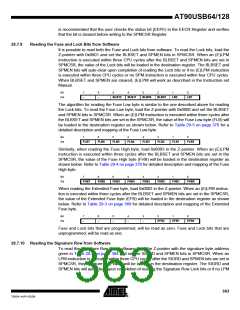
It is possible to read both the Fuse and Lock bits from software. To read the Lock bits, load the
Z-pointer with 0x0001 and set the BLBSET and SPMEN bits in SPMCSR. When an (E)LPM
instruction is executed within three CPU cycles after the BLBSET and SPMEN bits are set in
SPMCSR, the value of the Lock bits will be loaded in the destination register. The BLBSET and
SPMEN bits will auto-clear upon completion of reading the Lock bits or if no (E)LPM instruction
is executed within three CPU cycles or no SPM instruction is executed within four CPU cycles.
When BLBSET and SPMEN are cleared, (E)LPM will work as described in the Instruction set
Manual.
Bit
Rd
7
6
5
4
3
2
1
0
–
–
BLB12
BLB11
BLB02
BLB01
LB2
LB1
The algorithm for reading the Fuse Low byte is similar to the one described above for reading
the Lock bits. To read the Fuse Low byte, load the Z-pointer with 0x0000 and set the BLBSET
and SPMEN bits in SPMCSR. When an (E)LPM instruction is executed within three cycles after
the BLBSET and SPMEN bits are set in the SPMCSR, the value of the Fuse Low byte (FLB) will
be loaded in the destination register as shown below. Refer to Table 29-5 on page 370 for a
detailed description and mapping of the Fuse Low byte.
Bit
Rd
7
6
5
4
3
2
1
0
FLB7
FLB6
FLB5
FLB4
FLB3
FLB2
FLB1
FLB0
Similarly, when reading the Fuse High byte, load 0x0003 in the Z-pointer. When an (E)LPM
instruction is executed within three cycles after the BLBSET and SPMEN bits are set in the
SPMCSR, the value of the Fuse High byte (FHB) will be loaded in the destination register as
shown below. Refer to Table 29-4 on page 370 for detailed description and mapping of the Fuse
High byte.
Bit
Rd
7
6
5
4
3
2
1
0
FHB7
FHB6
FHB5
FHB4
FHB3
FHB2
FHB1
FHB0
When reading the Extended Fuse byte, load 0x0002 in the Z-pointer. When an (E)LPM instruc-
tion is executed within three cycles after the BLBSET and SPMEN bits are set in the SPMCSR,
the value of the Extended Fuse byte (EFB) will be loaded in the destination register as shown
below. Refer to Table 29-3 on page 369 for detailed description and mapping of the Extended
Fuse byte.
Bit
Rd
7
6
5
4
3
2
1
0
–
–
–
–
–
EFB2
EFB1
EFB0
Fuse and Lock bits that are programmed, will be read as zero. Fuse and Lock bits that are
unprogrammed, will be read as one.
28.7.10 Reading the Signature Row from Software
To read the Signature Row from software, load the Z-pointer with the signature byte address
given in Table 28-6 on page 364 and set the SIGRD and SPMEN bits in SPMCSR. When an
LPM instruction is executed within three CPU cycles after the SIGRD and SPMEN bits are set in
SPMCSR, the signature byte value will be loaded in the destination register. The SIGRD and
SPMEN bits will auto-clear upon completion of reading the Signature Row Lock bits or if no LPM
363
7593A–AVR–02/06

 ATMEL [ ATMEL ]