AT85C51SND3Bx
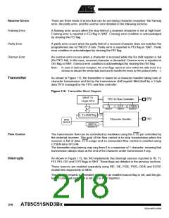
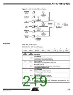
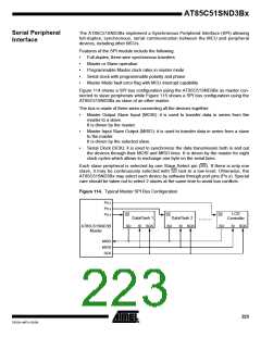
Figure 113. SIO Controller Interrupt System
RI
SINT.0
RIE
SIEN.0
TI
SINT.1
TIE
SIEN.1
FEI
SINT.2
SIO
Interrupt
Request
FEIE
SIEN.2
PEI
SINT.3
ES
IEN0.4
PEIE
SIEN.3
OEI
SINT.4
OEIE
SIEN.4
EOTI
SINT.5
EOTIE
SIEN.5
Registers
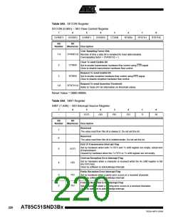
Table 242. SCON Register
SCON (0.91h) – SIO Control Register
7
6
5
4
3
2
1
0
SIOEN
PMOD1
PMOD0
PBEN
STOP
DLEN
GBIT1
GBIT0
Bit
Bit
Number
Mnemonic Description
SIO Enable Bit
7
6-5
4
SIOEN
PMOD1:0
PBEN
Set to enable the Serial Input/Output port.
Clear to disable the Serial Input/Output port.
Parity Mode Bits
Refer to Table 237 for information on parity mode
Parity Bit Enable Bit
Set to enable parity generation according to PMOD1:0 bits.
Clear to disable parity generation.
Stop Bit Number
3
2
STOP
DLEN
Set to enable generation of 2 stop bits.
Clear to enable generation of 1 stop bit.
Data Length Bit
Set to enable generation of 7 data bits.
Clear to enable generation of 8 data bits.
Guard Bit Number
1-0
GBIT1:0
Number of guard bits (from 0 to 3) transmitted after the last stop bit in
transmission mode.
Reset Value = 0000 0000b
219
7632A–MP3–03/06

 ATMEL [ ATMEL ]